Device for monitoring an area of coverage on a work tool

a technology for work tools and devices, applied in the direction of instruments, analogue processes for specific applications, using reradiation, etc., can solve the problems of assembly robots of this type presenting a high potential for danger, reducing the working cycle of assembly robots, and reducing the protection of other people in the area of coverag

Active Publication Date: 2005-09-22
ROCKWELL AUTOMATION TECH
View PDF4 Cites 72 Cited by
  • Summary
  • Abstract
  • Description
  • Claims
  • Application Information

AI Technical Summary

Benefits of technology

[0012] It is thus the object of the present invention to create a system which ensures a secure monitoring of an area of coverage around stationary as well as mobile work tools.
[0014] One critical advantage of the device according to the invention is that the camera not only supplies two-dimensional surface information of the area to be monitored, but also provides depth information based on the distance measurements carried out. As a result, an object can be detected within the area of coverage without realizing a reference image comparison. In particular, objects positioned in front of a background can be securely detected, wherein the object detection for the most part is independent of environmental influences such as the background composition or external light irradiation.
[0015] It is furthermore advantageous if the device according to the invention forms a compact structural module which can be used for monitoring areas of coverage around mobile and stationary work tools. The device according to the invention in particular can be installed on robot arms for covering the danger zone in the area surrounding the robot arm. The device according to the invention furthermore can be installed on transport vehicles, for example, industrial trucks, for monitoring the area in front of these vehicles.
[0017] Alternatively, safety-critical zones and non safety-critical zones can also be defined within the area of coverage, wherein only object detections in the non safety-critical zones will not result in deactivation of the work tool. By blanking out such areas, the availability of the work tool is increased because unnecessary shutdowns resulting from object detections in those areas are avoided.
[0019] The contours and, if necessary, also the paths of such non safety-critical objects are advantageously acquired in a learning process. During the operating phase following the learning process, all objects that do not match the acquired non safety-critical objects are then classified as safety-critical objects, so that their detection within the area of coverage results in a deactivation of the work tool. This ensures a maximum degree of safety when monitoring an area of coverage since only the previously acquired, non safety-critical objects do not result in deactivating the work tool entering the area of coverage.

Problems solved by technology

Assembly robots of this type represent a high potential for danger since the operator in general must insert the work pieces manually at the assembly robot.
The disadvantage of these devices is that other persons in the area of coverage are not protected.
An additional disadvantage with a work tool embodied as assembly robot is that the assembly robot working cycle decreases, thus unnecessarily restricting its availability.
However, protective devices of this type have the disadvantage that numerous such protective devices are required to completely secure an area of coverage around an assembly robot, particularly with respect to access protection and securing of the area.
Not only does this represent an undesirably high expenditure, but it also requires an expensive and involved assembly, wherein the available space for installing these devices is frequently insufficient.
It is a further disadvantage that these types of protective devices are not suitable for monitoring areas of coverage around mobile work tools.
The disadvantage of the above-mentioned invention is that the reference image comparison depends on the environment and is thus subject to interference.
External light influences in particular can lead to errors in the object detection.

Method used


Image

  • Device for monitoring an area of coverage on a work tool
  • Device for monitoring an area of coverage on a work tool
  • Device for monitoring an area of coverage on a work tool

Examples


Embodiment Construction

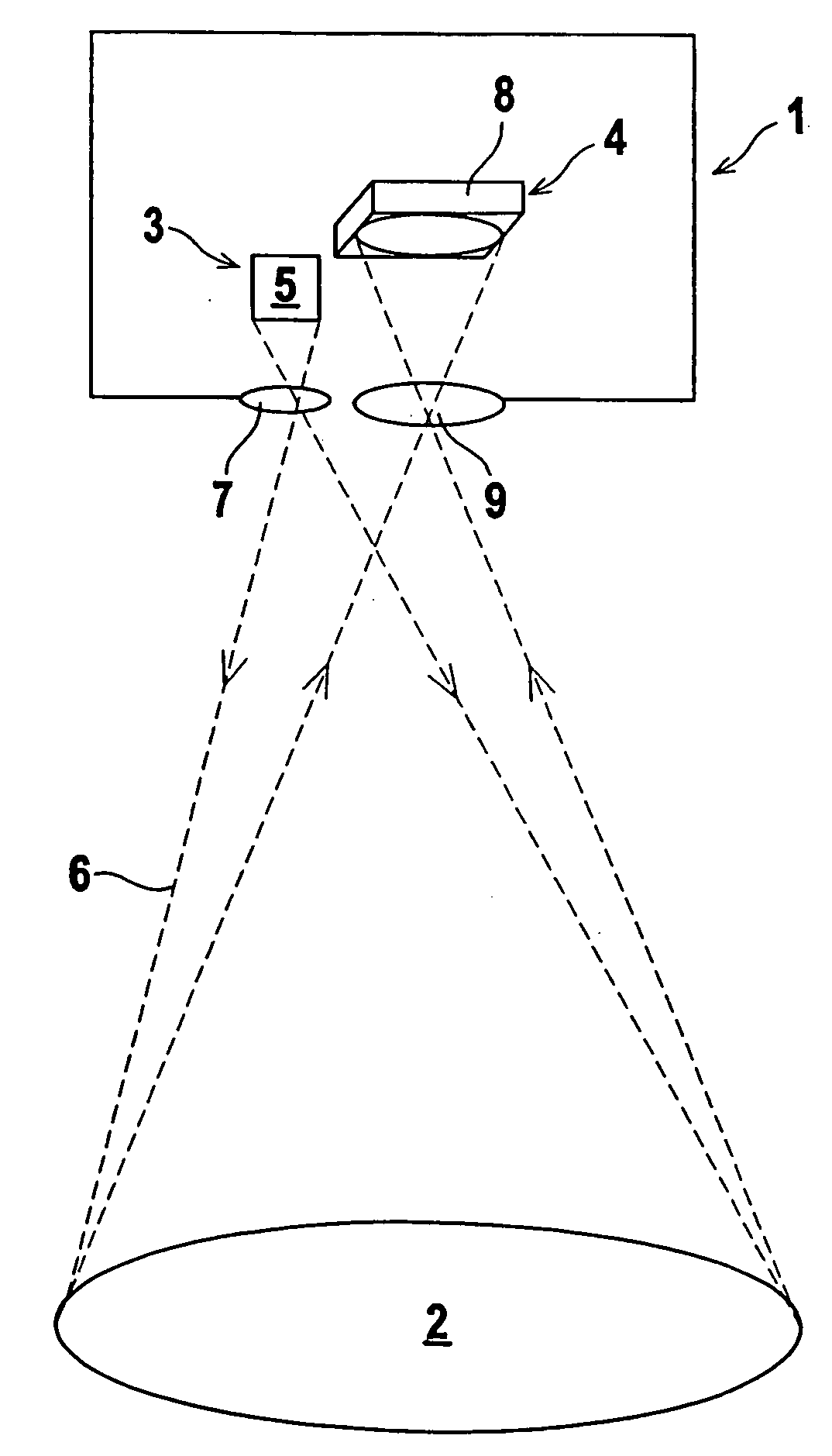
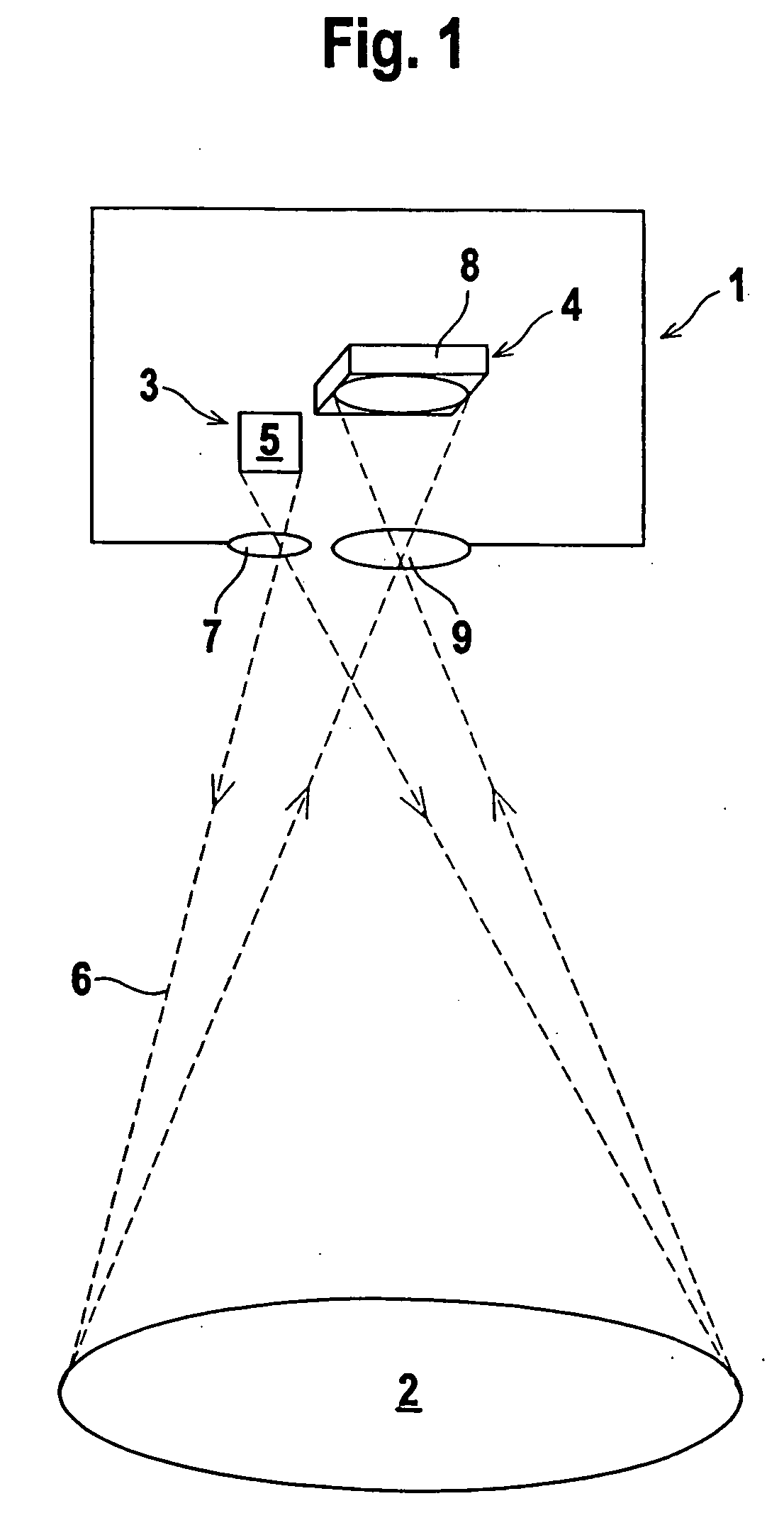
[0026]FIG. 1 schematically shows the optical components of a device 1 for monitoring an area of coverage 2 on a work tool. The work tool, which is not shown in FIG. 1, is a machine, a system, or a vehicle. As a result of operations carried out with this work tool, a danger zone is created in the region of the work tool. The device 1 is used for monitoring the danger zone within the area of coverage 2.

[0027] The optical components of the device 1 form a sensor unit, comprising a lighting unit 3 and a camera 4. The lighting unit 3 for the present case is provided with a transmitter 5 in the form of a laser diode which emits light rays 6. Alternatively, the transmitter 5 can also be embodied as light-emitting diode. The lighting device 3 can also consist of arrangements comprising several laser diodes or light-emitting diodes. As a further component, the lighting unit 3 comprises transmitting optics 7, installed downstream of the transmitter 5. The transmitting optics 7 realizes the b...


PUM


Abstract

A device for monitoring an area of coverage on a work tool may comprise a sensor, a camera, an evaluation unit, and at least one circuit output to activate the work tool only if no object is located in the area of coverage. The sensor may comprise a lighting unit to emit light rays to illuminate the area of coverage and a camera to detect three-dimensional images of the area of coverage, where the camera may include receiving elements in a matrix-type arrangement, the receiving elements to generate output signals. The evaluation unit is adapted to measure the output signals, to determine a distance value for each receiving element based on emitted light rays from the lighting unit traveling to the area of coverage and being reflected back.

Description

CROSS-REFERENCE TO RELATED APPLICATIONS [0001] This application is a continuation of U.S. patent application Ser. No. 11 / 015,762, filed on Dec. 20, 2004, which claims the priority of German Patent Application No. 103 60 174.0-52, filed Dec. 20, 2003, the disclosures of both of which are incorporated herein by reference.BACKGROUND OF THE INVENTION [0002] The invention relates to a device for monitoring an area of coverage on a work tool. [0003] The work tool can be a mobile system, wherein mobile systems of this type can be transport vehicles such as industrial trucks. With systems of this type, the area of coverage is the area in front of the transport vehicle which must be monitored to avoid collisions with persons or objects. The work tools can furthermore be stationary systems such as machines with machine parts that perform dangerous movements. The area of coverage must, therefore, be dimensioned so as to allow the monitoring of regions where endangering movements are carried ou...

Claims


Application Information

Patent Timeline
Patent Type & Authority Applications(United States)
IPC IPC(8): G01S17/89F16P3/14G01S17/04G06T7/00
CPCF16P3/14G01S17/026F16P3/144F16P3/142G01S17/89G01S17/04
Inventor LOHMANN, LUTZ
Owner ROCKWELL AUTOMATION TECH
Why Eureka
Try Eureka