
Method for controlling microbending induced attenuation losses in an optical fiber

a technology of optical fibers and attenuation losses, which is applied in the field of controlling the attenuation losses caused by microbending on the, and can solve the problems of fiber buckling inside the primary coating, delamination of the coating system, and undesirable attenuation of the transmitted signal

Inactive Publication Date: 2005-09-22
PRYSMIAN CAVI E SISTEMI ENERGIA
View PDF5 Cites 21 Cited by
  • Summary
  • Abstract
  • Description
  • Claims
  • Application Information

AI Technical Summary

Benefits of technology

[0027] The present method, when applied on a standard single mode optical fiber determines a microbending sensitivity on said fiber at 1550 nm at a temperature of −30° C. of less than 1.5 (dB/km)(g/mm)

Problems solved by technology

The coating system is selected to provide environmental protection to the glass fiber and resistance, inter alia, to the well-known phenomenon of microbending, which can lead to attenuation of the signal transmission capability of the fiber and is therefore undesirable.
As disclosed in said patent, a too low equilibrium modulus may cause fiber buckling inside the primary coating and delamination of the coating system.
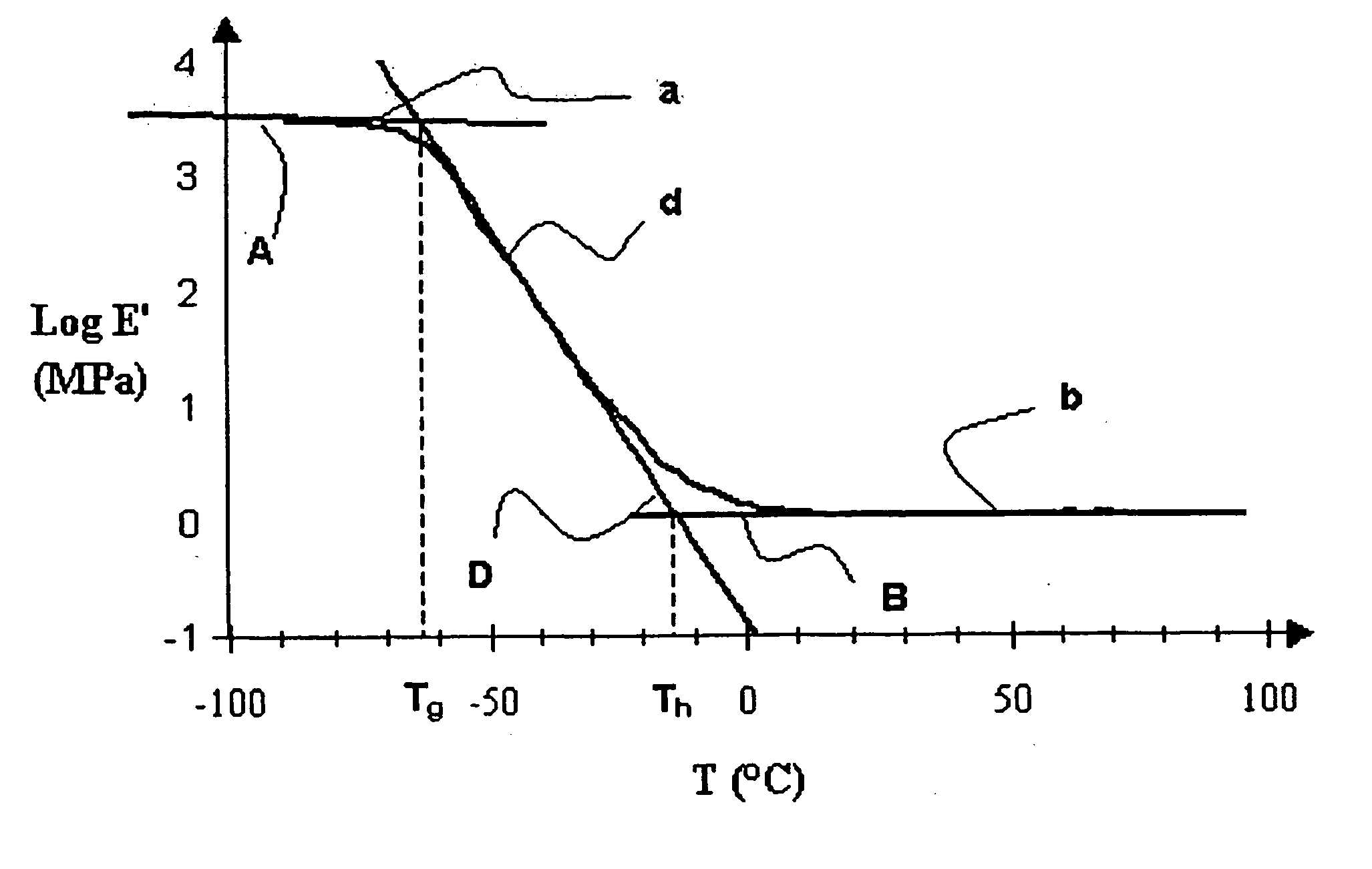
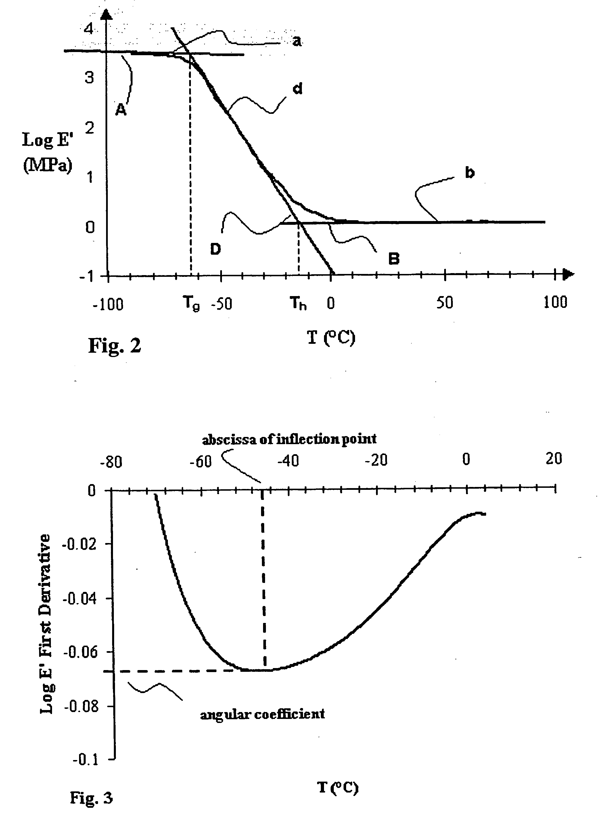
As a matter of fact, an excessive increase of the modulus of the primary coating upon temperature decrease may negatively affect the optical performances of the optical fiber, in particular at the low temperature values, thus causing undesirable attenuation of the transmitted signal due to microbending.
This problem is further worsened when the optical fibers are inserted into a cable structure, typically within a polymeric protecting sheath, which may in general take the form of a tube.

Method used


Image

  • Method for controlling microbending induced attenuation losses in an optical fiber
  • Method for controlling microbending induced attenuation losses in an optical fiber
  • Method for controlling microbending induced attenuation losses in an optical fiber

Examples


examples

[0169] The present invention will be explained in more detail below by way of examples, which are not intended to be limiting of the present invention.

[0170] Coating Compositions

[0171] Coating compositions have been prepared to be applied as primary coating on optical fibers. The compositions to be applied as a primary coating on an optical fiber according to the invention are indicated as Ex. 1, Ex. 2 and Ex. 3 in the following table 1.

TABLE 1Radiation curable primary coating compositionsEx. 1Ex. 2Ex. 3(Wt. %)(Wt. %)(Wt. %)Oligomer I68.3060.3067.30Ethoxylated nonyl phenol acrylate10.0019.0010.00Tridecyl acrylate10.0010.0010.00Long aliphatic chain-substituted2.002.002.00monoacrylateVinyl caprolactam5.006.005.00Ethoxylated bisphenol A diacrylate1.00—3.00Trimethylol propane triacrylate (TMPTA)1.00——2,4,6-trimethylbenzoyl diphenyl phosphine1.401.401.40oxideThiodiethylene bis [3-(3,5-di-tert-butyl-4-0.300.300.30hydroxyphenyl) propionate]) hydrocinnamateγ-mercapto propyl trimethoxysi...


PUM

PropertyMeasurementUnit
Temperatureaaaaaaaaaa

Abstract

A method for controlling attenuation losses caused by microbending on the signal transmitted by an optical fiber having an internal glass portion. A first coating layer of a first polymeric material surrounds the glass portion and a second coating layer of a second polymeric material surrounds the first coating layer. The first polymeric material has a hardening temperature lower than 10° and an equilibrium modulus lower than 1.5 MPa.

Description

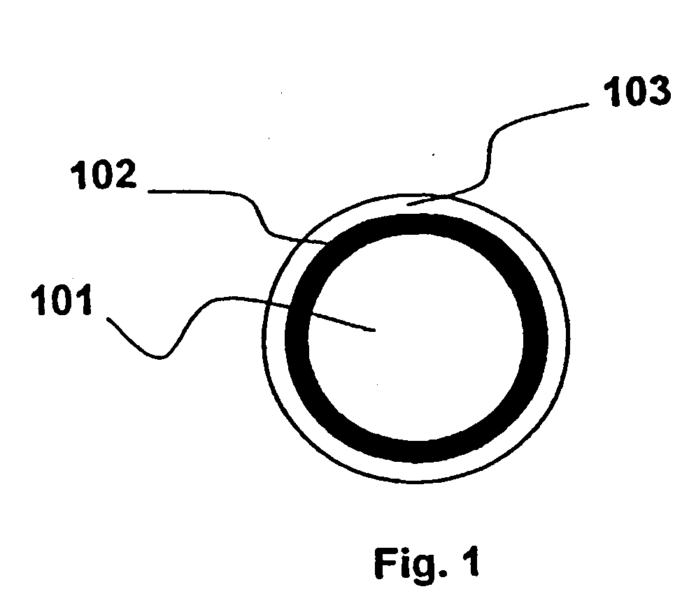
FIELD OF THE INVENTION [0001] The present invention relates to a method for controlling the attenuation losses caused by microbending on the signal transmitted by an optical fiber. BACKGROUND ART [0002] Optical fibers commonly consist of a glass portion (typically with a diameter of about 120-130 μm), inside which the transmitted optical signal is confined, The glass portion is typically protected by an outer coating, typically of polymeric material. This protective coating typically comprises a first coating layer positioned directly onto the glass surface, also known as the “primary coating”, and of at least a second coating layer, also known as “secondary coating”, disposed to surround said first coating. In the art, the combination of primary coating and secondary coating is sometimes also identified as “primary coating system”, as both these layer are generally applied during the drawing manufacturing process of the fiber, in contrast with “secondary coating layers” which may b...

Claims


Application Information

Patent Timeline
IPC IPC(8): C03C25/10C03C25/1065G02B6/02G02B6/44
CPCG02B6/02395C03C25/1065G02B6/44G02B6/02
Inventor ROBA, GIACOMO STEFANOTERRUZZI, LIDIAFOGLIANI, SABRINAARIMONDI, MARCONAGELVOORT, SANDRA JOANNAVAN EEKELEN, JOHANNES ADRIANUSABEL, ADRIANUS GIJSBERTUS MARIAGEUS, GOUKE DIRK JANALKLMA, DUURT PLETER WILLEM
Owner PRYSMIAN CAVI E SISTEMI ENERGIA
Learn More