

Durable electrophotographic prints
a toner fusing and electrophotography technology, applied in the direction of electrographic process apparatus, optics, instruments, etc., can solve the problems of high gloss prints made by electrophotographic reproduction apparatus, can be easily damaged by customers, and the fused toner image on the receiver member can suffer cracking damage, etc., to achieve uniform gloss in pictorial areas and differential gloss
- Summary
- Abstract
- Description
- Claims
- Application Information
AI Technical Summary
Benefits of technology
Problems solved by technology
Method used
Image

Examples
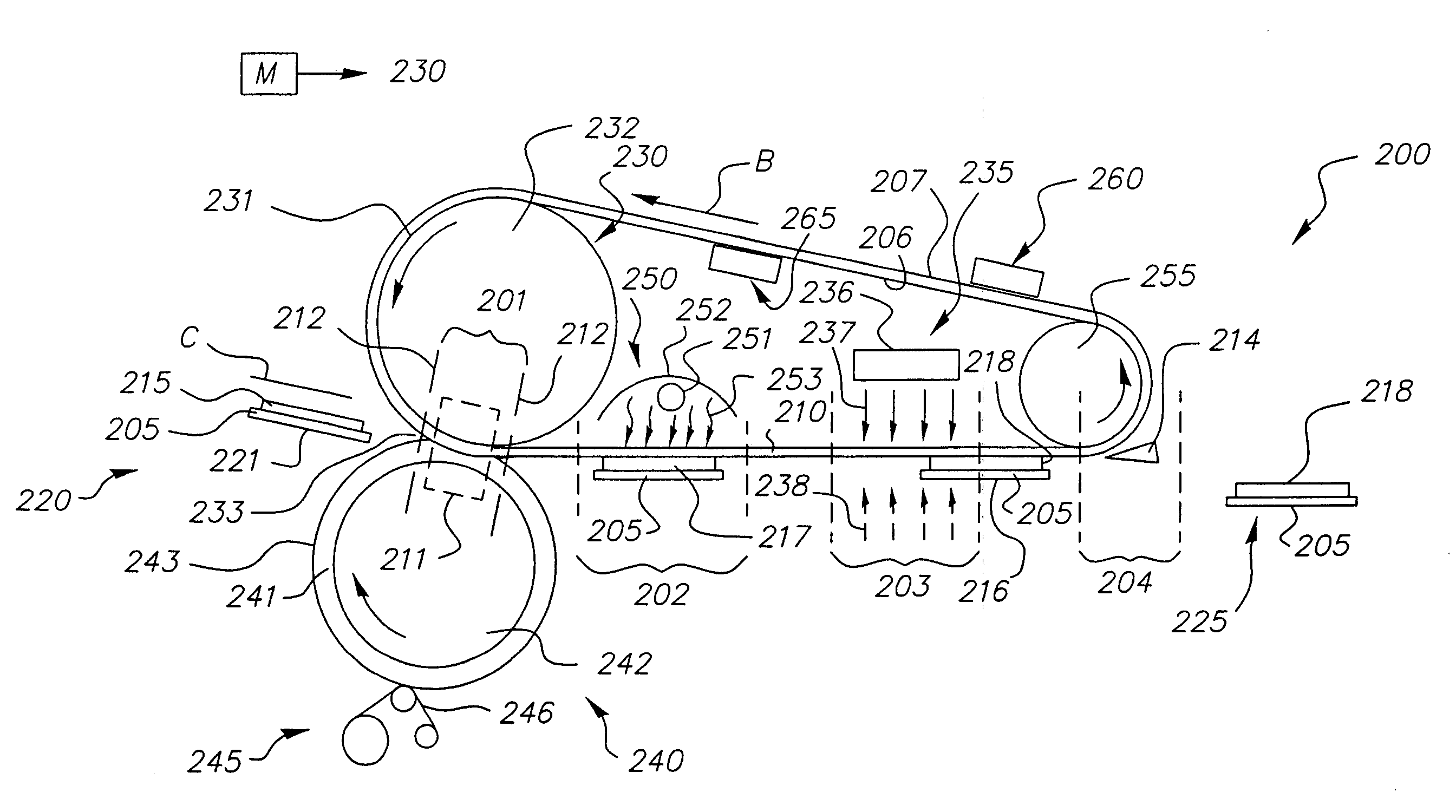
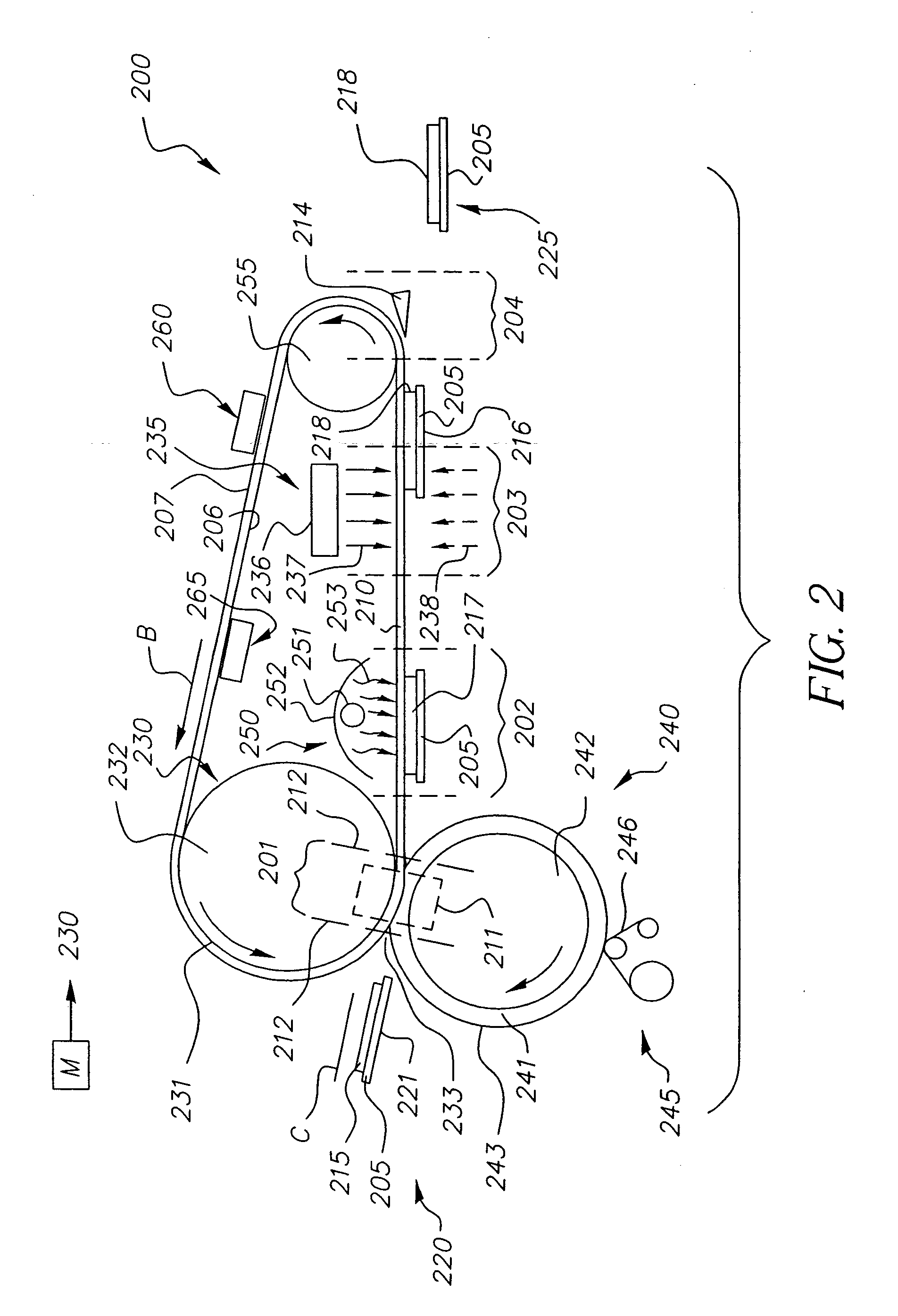
embodiment 200
[0068] In embodiment 200, the heating mechanism in heating zone 201 includes the hot contact area of the nip 233 (shown enclosed in FIG. 2 by the dotted line 211). The heating zone 201 can extend beyond the contact area of the nip, as indicated by the dashed lines 212, e.g., because of heat radiated outside of the nip by roller 230. Furthermore, a post-nip wrap of belt 210 around roller 230 can be provided so as to extend the heating zone beyond the actual contact area of the nip (post-nip wrap not illustrated).
[0069] Roller 230 is required to be sufficiently hot so as to melt at least UV-curable toner in contact with surface 207 of belt 210. Moreover, fusing temperature in nip 233 must be high enough so that the molten state of UV-curable toner persists while receiver member 205 is moved toward and into the exposure zone 202. However, with a UV-curable colorless or clear toner outermost in pre-gloss toner image 215, it is preferred that melted outermost toner particles do not flow ...
embodiment 500
[0088] To make a duplex glossed print in embodiment 500, a stack simplex prints can taken from tray 520 and put through a conventional electrophotographic reproduction apparatus (not shown) so as to form on each of the opposite faces a new pre-gloss toner image, and the stack returned to accessory unit 500 for these pre-gloss toner images to be glossed in manner as described above for the simplex prints. Preferably, for making duplex UV-glossed prints, each of the sheets initially placed in stack 512 has on each face a preferably pre-fused pre-gloss image, so that after one set of faces has been UV-glossed, the output members from the first glossing are removed from tray 520 and placed into housing 511 so that in a second glossing the opposing faces can be UV-glossed. To make “mixed” prints, simplex UV-glossed output members are delivered from tray 520 to a conventional electrophotographic reproduction apparatus (not shown) so that non-glossed toner images can be formed on the oppos...
embodiment 550
[0099]FIGS. 7a, b show block diagram sketches featuring an accessory unit embodiment 550 which includes UV-glossing apparatus of the invention for making simplex and duplex prints. Accessory 550 is preferably used as a stand-alone “near-line” unit, but is not restricted to such usage. Within unit 550 are included a UV-glossing (UVG) apparatus 552 of the invention and a colorless toner module (CTM) 551.
[0100]FIG. 7a illustrates how embodiment 550 can be used to UV-gloss one side of an input member (RS) 565, which is a receiver member carrying a simplex color toner image. This color toner image is preferably made from conventional (non-UV-curable) color toner, which color toner is preferably fused. Input member RS is moved along path k, into the accessory 550 and is first processed by being passed through the colorless toner module 551. In CTM 551, a layer of preferably colorless UV-curable toner particles is deposited in juxtaposition with the simplex color toner image, following whi...
PUM
 Abstract
Description
Claims
Application Information