Antireflection film, production process of the same, polarizing plate and image displaying apparatus
a technology of anti-reflection film and production process, which is applied in the direction of thin material processing, instruments, coatings, etc., can solve the problems of insufficient anti-fouling property of the low refractive index layer, the inability to meet simultaneously all the low refractive index, and the inability to produce suitable products, etc., to achieve the effect of reducing production costs, reducing production costs, and ensuring anti-fouling ability and abrasion resistan
- Summary
- Abstract
- Description
- Claims
- Application Information
AI Technical Summary
Benefits of technology
Problems solved by technology
Method used
Image
Examples
example 1
1-1 Coating of Hardcoat Layer A and Hardcoat Layer C
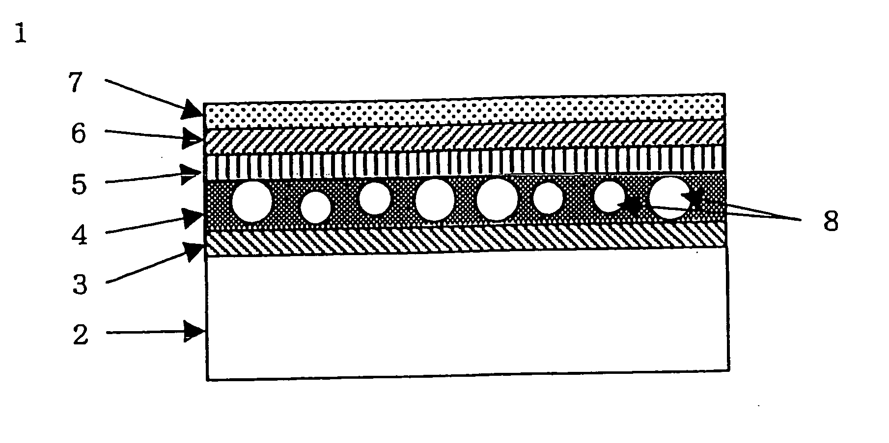
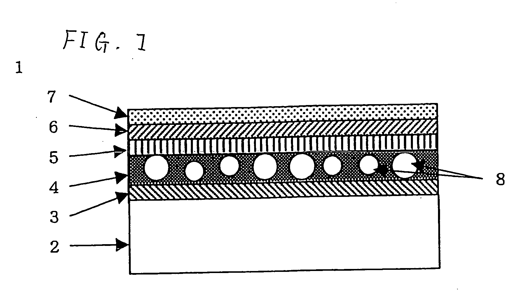
[0245] A rolled triacetyl cellulose film (TD80U, produced by Fuji Photo Film Co., Ltd.) as a support was wound off, on which the coating solution for a hardcoat layer was directly coated by using a microgravure roll of 50 mm in diameter having a gravure pattern with a line number of 180 per inch and a depth of 40 μm at a conveying speed of 30 m / min, and then dried at 60° C. for 150 seconds. The coated layer was cured by irradiating with an ultraviolet ray under a nitrogen purged atmosphere by using an air-cooled metallic halide lamp of 160 W / cm (produced by Eyegraphics Co., Ltd.) at an illuminance of 400 mW / cm2 to an irradiance of 250 mJ / cm2 for the hardcoat layer A or 300 mJ / cm2 for the hardcoat layer C, so as to form a hardcoat layer, followed by winding the support. The rotation speed of the gravure roll was adjusted in such a manner that the thickness of the hardcoat layer after curing became 6 μm for the hardcoat layer A or ...
example 2
[0287] A polarizing plate having an antireflection film was produced by adhering the sample film of Example 1 to a polarizing film. A liquid crystal display device was produced by using the polarizing plate with the antireflection film disposed as the outermost layer. The liquid crystal display device suffered less reflection of outside light with indistinct reflected images to provide excellent visibility. The liquid crystal display device satisfied all the antifouling property, the dust adhesion resistance and the abrasion resistance, which were to be considered upon practical use.
[0288] It is also understood from comparison between the samples No. 007 and No. 008 and comparison between samples No. 011 and No. 012 that the coating and curing method using both thermal curing and ionizing radiation curing in combination provides favorable results, and thus further improved results can be obtained among the inventive samples by suitably combining the materials and the production pro...
example 3
[0289] A triacetyl cellulose film (TAC-TD80U, produced by Fuji Photo Film Co., Ltd.) having a thickness of 80 μm was immersed in a 1.5 mole / L sodium hydroxide aqueous solution at 55° C. for 2 minutes, and then neutralized and washed with water. A polarizing film was produced by adsorbing iodine to a polyvinyl alcohol film, followed by stretching. The triacetyl cellulose film and the antireflection film of Example 1 were adhered on both surfaces of the polarizing film for protecting the film to produce a polarizing plate. A polarizing plate on the viewing side of a transmission TN liquid crystal display device (having a polarization split film having a polarization selecting layer, D-BEF, produced by Sumitomo 3M, Ltd., between a backlight and liquid crystal cells) of a notebook computer was replaced by the polarizing plate thus obtained, so as to expose the antireflection film side of the polarizing plate as the most superficial aspect. The display device suffered less reflection of ...
PUM
 Abstract
Description
Claims
Application Information
 - R&D
- Intellectual Property
- Life Sciences
- Materials
- Tech Scout
- Unparalleled Data Quality
- Higher Quality Content
- 60% Fewer Hallucinations
Browse by: Latest US Patents, China's latest patents, Technical Efficacy Thesaurus, Application Domain, Technology Topic, Popular Technical Reports.
© 2025 PatSnap. All rights reserved.Legal|Privacy policy|Modern Slavery Act Transparency Statement|Sitemap|About US| Contact US: help@patsnap.com


