
System and methodology for vibration analysis and condition monitoring

a technology of condition monitoring and vibration analysis, applied in the field of rotating machine analysis, can solve the problems of operational problems, maintenance or repair, and the existence of operational problems, and achieve the effect of rapid and inexpensive implementation

Inactive Publication Date: 2005-09-22
EXXON RES & ENG CO
View PDF1 Cites 40 Cited by
  • Summary
  • Abstract
  • Description
  • Claims
  • Application Information

AI Technical Summary

Benefits of technology

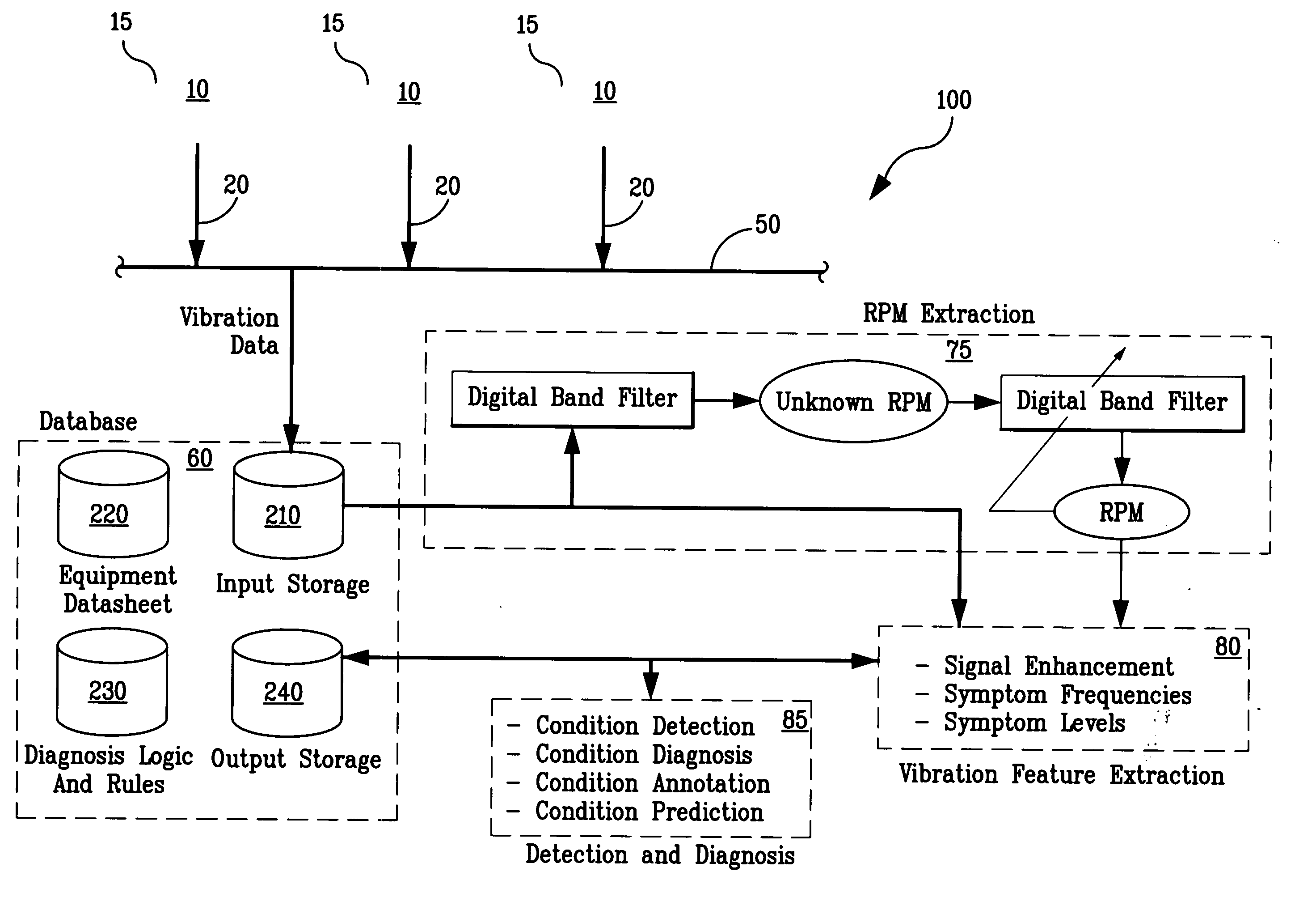
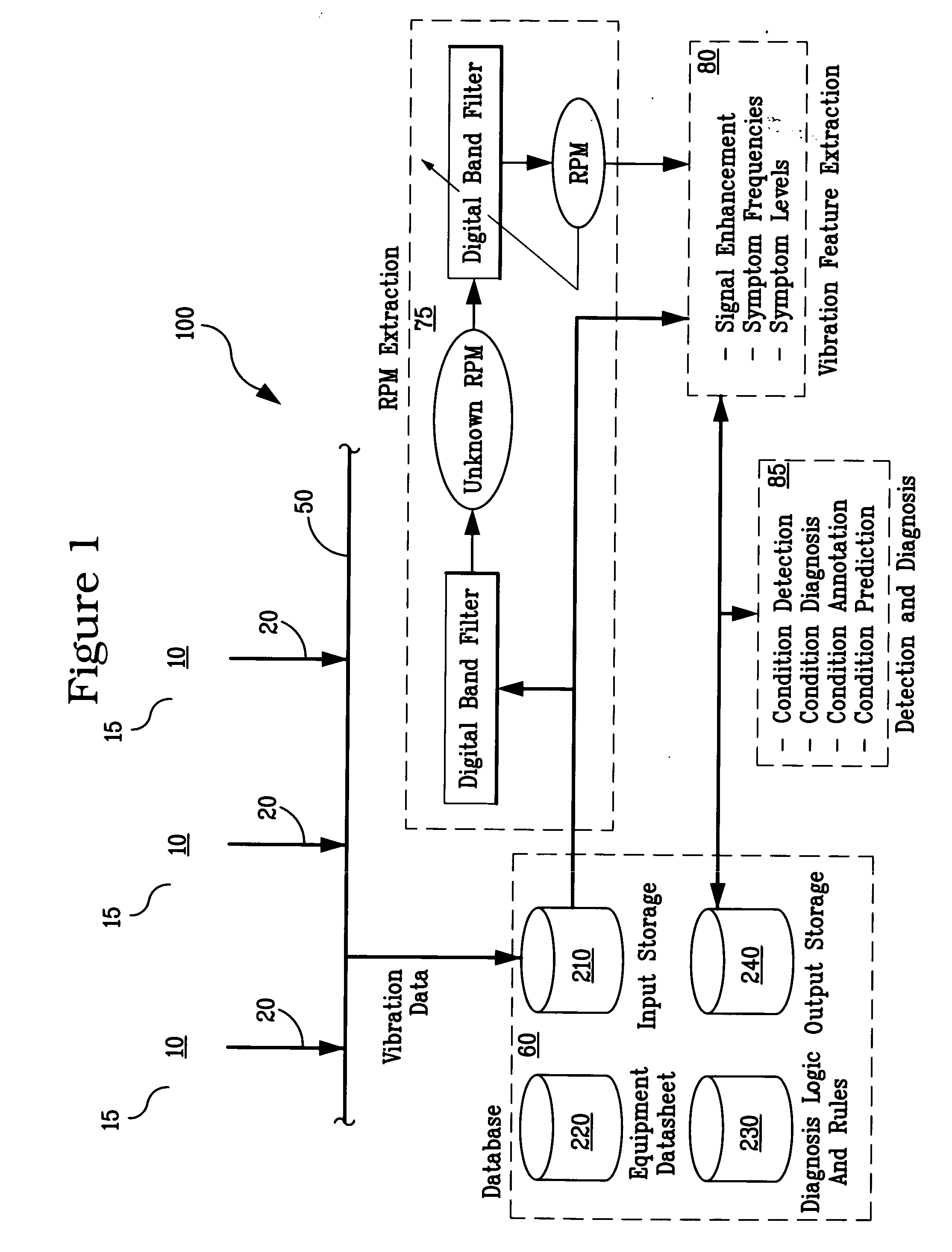
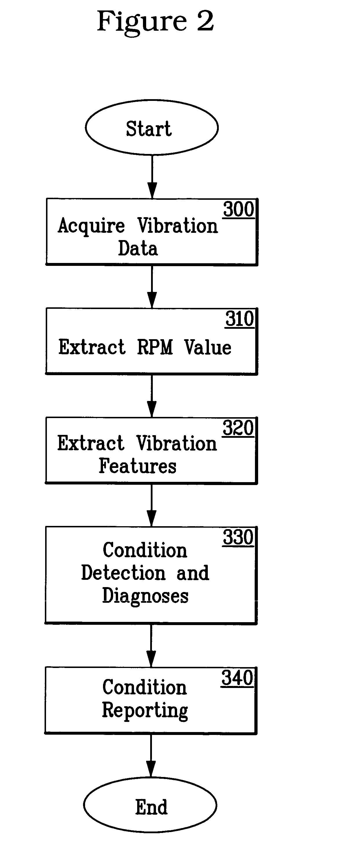
The present invention is a system and method for continuously monitoring the condition of rotating equipment. It uses adaptive signal processing techniques to determine the speed of the machine from the vibration data collected from a vibration transducer mounted on the machine. This allows for real-time analysis of the machine's condition. The invention extracts characteristic vibration features from the vibration data and uses them to detect and diagnose machine faults. Unlike other methods, the invention does not require expensive additional hardware or machine shutdowns. It can be quickly and efficiently implemented on both new and existing machines and can be applied to multiple machines simultaneously. The invention offers a cost-effective solution for accurate speed monitoring and continuous fault monitoring of rotating machines.

Problems solved by technology

As manufacturing and processing requirements become more and more complex, today's plants and other manufacturing and processing facilities contain more and more machines and other complex mechanical components and devices of all sizes and shapes and for an exceedingly large variety of applications.
For example, significant deviations in RPM speed from that which is called for in the machine specification may indicate the existence of an operational problem.
Also, significant deviation from the past characteristic operating RPM speed for a particular machine may signal that some form of maintenance or repair is required.
As yet another example, known operational problems may be suspected based upon vibration information as the vibration frequency spectrum of the machine relates to the rotational speed of the machine.
The presence of excessive vibration levels at certain frequencies, known as defect or fault frequencies, usually indicates a specific machine fault or operational problem.
For example, a high vibration at a frequency of 1×RPM may be caused by an unbalance of the machine shaft.
Additionally, inaccurate RPM readings can lead to misdiagnosis of a machine problem.
Unfortunately, these RPM sensors are quite difficult to install on existing machines.
Further, the sensors are quite expensive and given the large numbers of machines in typical plants, which can number in the thousands, the costs can be prohibitive.
It is for this reason that direct speed sensor measurement is often limited to a few critical machines such as major process compressors in a refinery application.
This method, however, typically requires an operator to interpret the FFT spectrum and is not, therefore, suitable for automatic on-line vibration analysis.
These vibration monitoring systems are usually equipped with only vibration sensors and not with speed sensors because of cost constraints.
Further, the majority of low-cost on-line vibration monitoring systems are not capable of providing high-resolution FFT vibration analysis.
Without direct RPM sensors, the vibration monitoring systems currently in use are relatively inaccurate in terms of providing RPM readings.
However, many of these techniques still suffer from drawbacks including inaccuracy in RPM readings.
In particular, these techniques often result in inaccurate readings especially when the noise associated with the vibration readings is high—a common situation in most plant applications.
However, the accuracy of the method is limited to the frequency resolution, amplitude accuracy and background noise in the vibration frequency spectrum.
The FFT technique employed to obtain the vibration frequency spectrum is inherently inaccurate due to the spectrum smearing or energy leakage in determining the true peak values of the vibration.
Many low-cost data acquisition systems can only provide relatively low resolution of the FFT spectrum.
In addition, the FFT technique of Hicho's method neglects the essential phase information of the vibration components and is not effective in suppressing the random noise when compared with averaging techniques in time domain such as “synchronous averaging”.
Another difficulty with this method is that the selection of a criterion to identify the peaks from the vibration frequency spectrum is arbitrary.
This method has the same limitations as Hitcho's method because it also operates on the FFT spectrum.
If a machine fault develops, the dynamic processes in the machine change and some of the forces acting on and within the machine therefore change.
However, at the same time, these machine operators and service personnel are subject to data overload given these new systems.

Method used


Image

  • System and methodology for vibration analysis and condition monitoring
  • System and methodology for vibration analysis and condition monitoring
  • System and methodology for vibration analysis and condition monitoring

Examples


application example

[0073] In order to further illustrate the RPM extraction subsystem and the method of the present invention, a real-world application example is now provided wherein raw vibration data was acquired for two motor-driven pumps in order to test system performance. In this case, the design speeds for both pumps were 3600 RPM. Using a speed resolution of + / −1 RPM, the pump speeds were measured by the system of the present invention to be 3538 RPM for Pump 1 and 3579 RPM for Pump 2.

[0074]FIG. 8 illustrates the vibration waveforms and frequency spectrums for both Pump 1 and Pump 2. The pumps have significantly different vibration characteristics in that Pump 1 exhibits a fairly simple spectrum with dominantly low frequency vibration while Pump 2 generates a very complex spectrum with excessive high frequency components and a significant amount of broadband noise. There is also a substantial amount of DC noise in the spectrums due to the integration of the data acquisition system during the...


PUM


Abstract

A system and methodology for the continuous condition monitoring of rotating equipment. The present invention comprises a method that employs adaptive signal processing techniques to determine the RPM of a rotating machine from the time-based vibration data. According to a preferred embodiment of the present invention, RPM is determined based upon the input of a digitized time-based sample sequence of vibration data acquired directly from a vibration transducer mounted on the machine for on-line real-time measurement of the machine RPM. Alternatively, the input to the “virtual RPM sensor” could come from a database or file where the sample sequences of the vibration signal are stored for off-line measurement of the machine RPM. Once RPM is determined, online vibration analysis for a given RPM or set of RPMs may be performed. The present invention extracts characteristic vibration features from vibration data and uses these extracted values to provide condition detection and diagnoses of machine faults.

Description

CROSS REFERENCE TO RELATED APPLICATIONS [0001] This application is a continuation-in-part application of a currently pending patent application entitled “Virtual RPM Sensor”, application Ser. No. 10 / 439,959, filed on 16 May 2003 and claims priority to provisional application Ser. No. 60 / 387,274 filed on Jun. 7, 2002, and the contents of each are hereby incorporated by reference in their entirety.FIELD OF THE INVENTION [0002] The present invention relates generally to the analysis of rotating machines and more particularly to techniques for determining operating faults present in such machines. BACKGROUND OF THE INVENTION [0003] As manufacturing and processing requirements become more and more complex, today's plants and other manufacturing and processing facilities contain more and more machines and other complex mechanical components and devices of all sizes and shapes and for an exceedingly large variety of applications. For example, in a typical petroleum refinery or other chemic...

Claims


Application Information

Patent Timeline
Patent Type & Authority Applications(United States)
IPC IPC(8): G01P3/44
CPCG01P3/44
Inventor SONG, LIMIN
Owner EXXON RES & ENG CO
Learn More