Heat resistant foam-in-bag packaging

a foam-in-bag, heat-resistant technology, applied in the field of foam-in-bag packaging, can solve the problems of not being desirable or feasible to have an extensive system, and not being able to meet the needs of every potential user. achieve the effect of improving the efficiency and speed at which articles can be packaged, and improving the cushion separation

Inactive Publication Date: 2005-09-29
SEALED AIR U S
View PDF33 Cites 7 Cited by
  • Summary
  • Abstract
  • Description
  • Claims
  • Application Information

AI Technical Summary

Benefits of technology

[0012] It has been found that varnishes and resins that can be crosslinked or thermoset are particularly useful as heat resistant coatings. In particular, flexographic and gravure inks having self-adhesion temperatures in excess of 275° F. can be applied to the surface of the thermoplastic bags in a sufficient weight to prevent the cushions from fusing together during foam formation. Typically, the inks are solvent-based, water-based, or energy cured. The addition of silicone to the heat resistant coating improves cushion separation.
[0013] Foam-in-bag products having heat resistant coatings that are in accordance with the invention are adeptly suited to prevent foam cushions from fusing together during packaging. As a result, the foam-in-bag cushions will eliminate many of the problems associated with the high temperatures that can be produced during foam formation and should improve the efficiency and speed at which articles can be packaged.

Problems solved by technology

The packaging requirements of various users may often differ and typically no one packaging system can meet the needs of every potential user.
It may not always be desirable or feasible to have an extensive system for preparing the bags or injecting foam precursors into a bag.
As a result, the cushions can be difficult to separate, and the article could be damaged during cushion separation.
Separating the cushions can create inefficiencies in the packaging system and make it more difficult to achieve packaging that conforms to the shape of the article.
These composite high-temperature films tend to be expensive and difficult to fabricate.
They also tend to be stiff and crinkly, and have high tear propagation.
In addition, they can be difficult to use in foam-in-bag machines because they cannot be readily cut with a hot cross cut wire on existing equipment.

Method used


Image

  • Heat resistant foam-in-bag packaging
  • Heat resistant foam-in-bag packaging
  • Heat resistant foam-in-bag packaging

Examples


Embodiment Construction

[0022] The invention now will be described more fully hereinafter with reference to the accompanying drawings, in which some, but not all embodiments of the invention are shown. Indeed, the invention may be embodied in many different forms and should not be construed as limited to the embodiments set forth herein; rather, these embodiments are provided so that this disclosure will satisfy applicable legal requirements. Like numbers refer to like elements throughout.

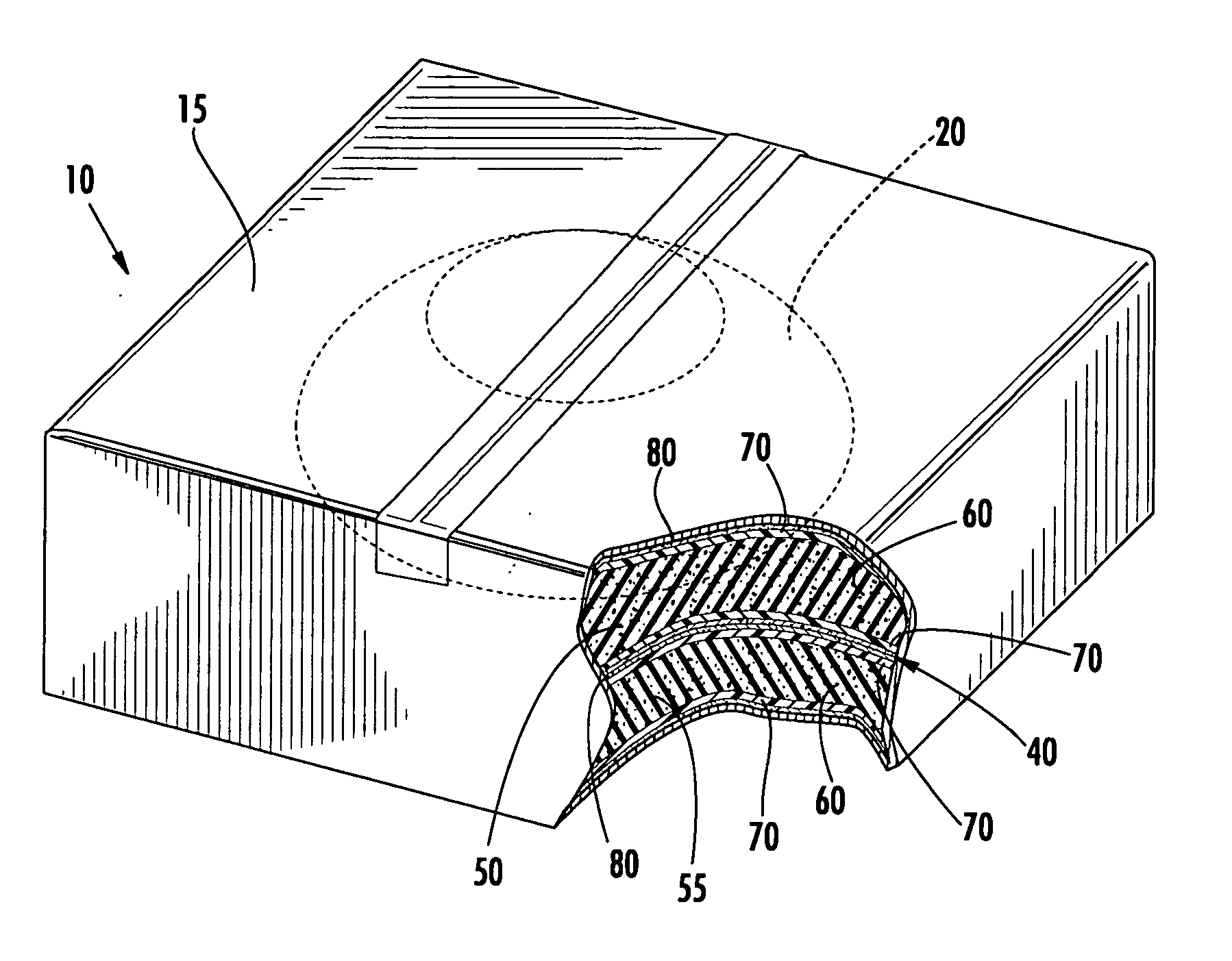
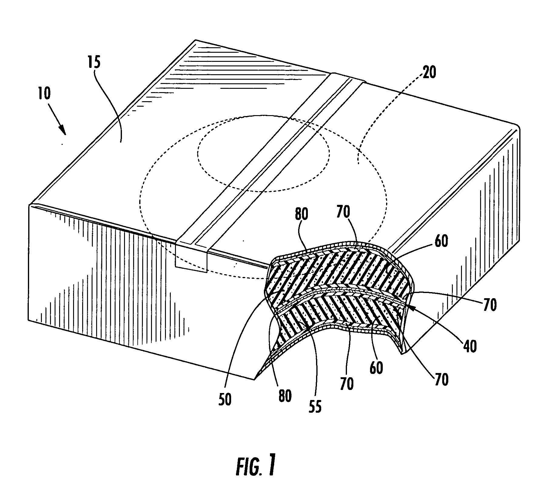
[0023] Referring now to the drawings, there is shown in FIG. 1 a cross-sectional view of an article packaged in a container and sandwiched between two foam-in-bag cushions, which is broadly designated by reference number 10. The article 20 is placed in a container 15 between a first foam-in-bag cushion 50 and a second foam-in-bag cushion 55. As shown, the cushions 50, 55 are in contact with each other at 40.

[0024]FIG. 1 illustrates a pair of foam cushions 50, 55 that are in accordance with the invention. The foam cushio...


PUM

PropertyMeasurementUnit
self-adhesion temperatureaaaaaaaaaa
weightaaaaaaaaaa

Abstract

The invention is a thermoplastic film having a heat resistant coating. The film is particularly useful in the preparation of bags and associated packaging systems that are used for protecting and packaging articles. Typically, the heat resistant coating has a melting range that is greater than the melting temperature of the thermoplastic film and exceeds the temperature of the heat generated during foam formation. As such, packaging films and bags that are prepared in accordance with the invention help prevent foam-in-bag cushions from fusing together. Particularly useful heat resistant coatings include ink varnishes and resins that are solvent-based, water-based, or energy cured.

Description

BACKGROUND OF THE INVENTION [0001] The invention relates generally to foam-in-place packaging systems, and in particular to foam packaging products that are prepared from mixing foam precursors together to form a foam. [0002] Foam-in-place packaging is a technique for producing cushioning that is used in the packaging of fragile articles to be shipped. Foam-in-place packaging comprises generating foam cushioning on an as needed basis while the article to be protected is being packaged. In general, foam-in-place packaging employs foamable compositions that are produced by mixing two or more precursor chemicals that react to form a polymer foam that hardens on curing. For example, a liquid polyol-containing precursor and a liquid isocyanate-containing precursor may be mixed and reacted to form a polyurethane foam. The resulting foam occupies a volume that is many times the volume of the liquid precursors. [0003] One technique for foam-in place packaging is to place the article to be p...

Claims


Application Information

Patent Timeline
Patent Type & Authority Applications(United States)
IPC IPC(8): B29C44/18B65B23/00B65D30/08B65D65/38B65D81/03
CPCB29C44/183Y10T428/1334B29C44/184Y10T428/249953Y10T428/249989
Inventor MAHON, WILLIAM JOSEPHOBERLE, TIMOTHY THEODOREBOWEN, JOE MILTONWHEELER, ROBERT DON
Owner SEALED AIR U S
Why Eureka
Try Eureka