Microresonator-based high-performance high-pressure sensor and system

a high-performance, sensor technology, applied in the direction of optical radiation measurement, instruments, manufacturing tools, etc., can solve the problems of severe and negative impact, limited application of quartz pressure transducers, and difficult to achieve the effect of reducing the size of quartz technology

Inactive Publication Date: 2005-09-29
FLIR DETECTION
View PDF3 Cites 25 Cited by
  • Summary
  • Abstract
  • Description
  • Claims
  • Application Information

AI Technical Summary

Problems solved by technology

However, there are several problems with quartz pressure sensing technologies that trigger motivation to seek new methods to address these needs.
Quartz pressure transducers appear to be limited for applications by higher pressure due to mechanical “twinning” of the pressure sensitive crystal element.
A target diameter of one-half inch or less is desirable to support horizontal operations; such size reductions are difficult for quartz technology to achieve.
Crystal manufacturers that previously provided the special purpose elements used in the quartz sensors as an adjunct to the more volume-oriented frequency control business have been severely and negatively impacted by this migration.
The development expense is increased by the reluctance of crystal manufacturers to participate in specialty crystal design given the minimal potential market.
The lifetime of quartz pressure transducers was, perhaps, underestimated since many existing tools date from the original production.
The severe environment dictates that extensive efforts must be made to protect the equipment.
These measures contribute to the expense of the transducer.
The certification process is time consuming and adds to the transducer cost.
However, under very high pressure, several deformation mechanisms, such as mechanical twinning and creeping, may occur in the crystal lattice structure.
These pressure-induced defects cause the failure of those quartz-based pressure sensors.
Finally, yet importantly, it is almost impossible for the quartz transducer to perform direct sensing without the translation of a force collector such as a bellows or Bourdon tube because quartz has no tolerance to the surface contamination.
The introduction of a force collector not only injects hysteresis and noise but also complicates the design.
However, due to its limited Q factor (˜1E4 or lower) it is difficult to provide enough measurement resolution because of its broad spectral feature.
With limited pressure sensitivity and spectral resolution, the FBG is less appealing in the high-resolution pressure sensing.

Method used


Image

  • Microresonator-based high-performance high-pressure sensor and system
  • Microresonator-based high-performance high-pressure sensor and system
  • Microresonator-based high-performance high-pressure sensor and system

Examples


Embodiment Construction

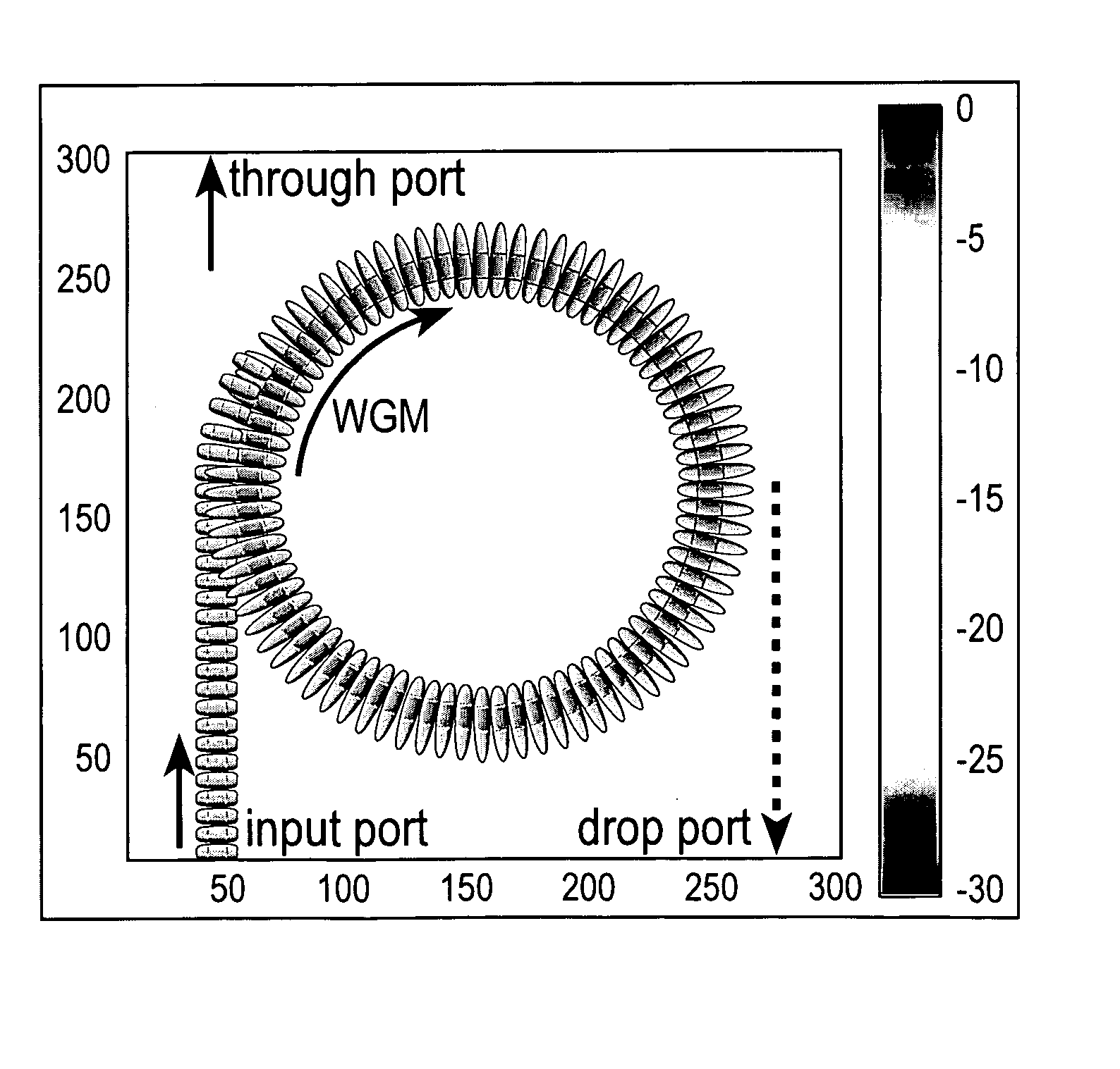
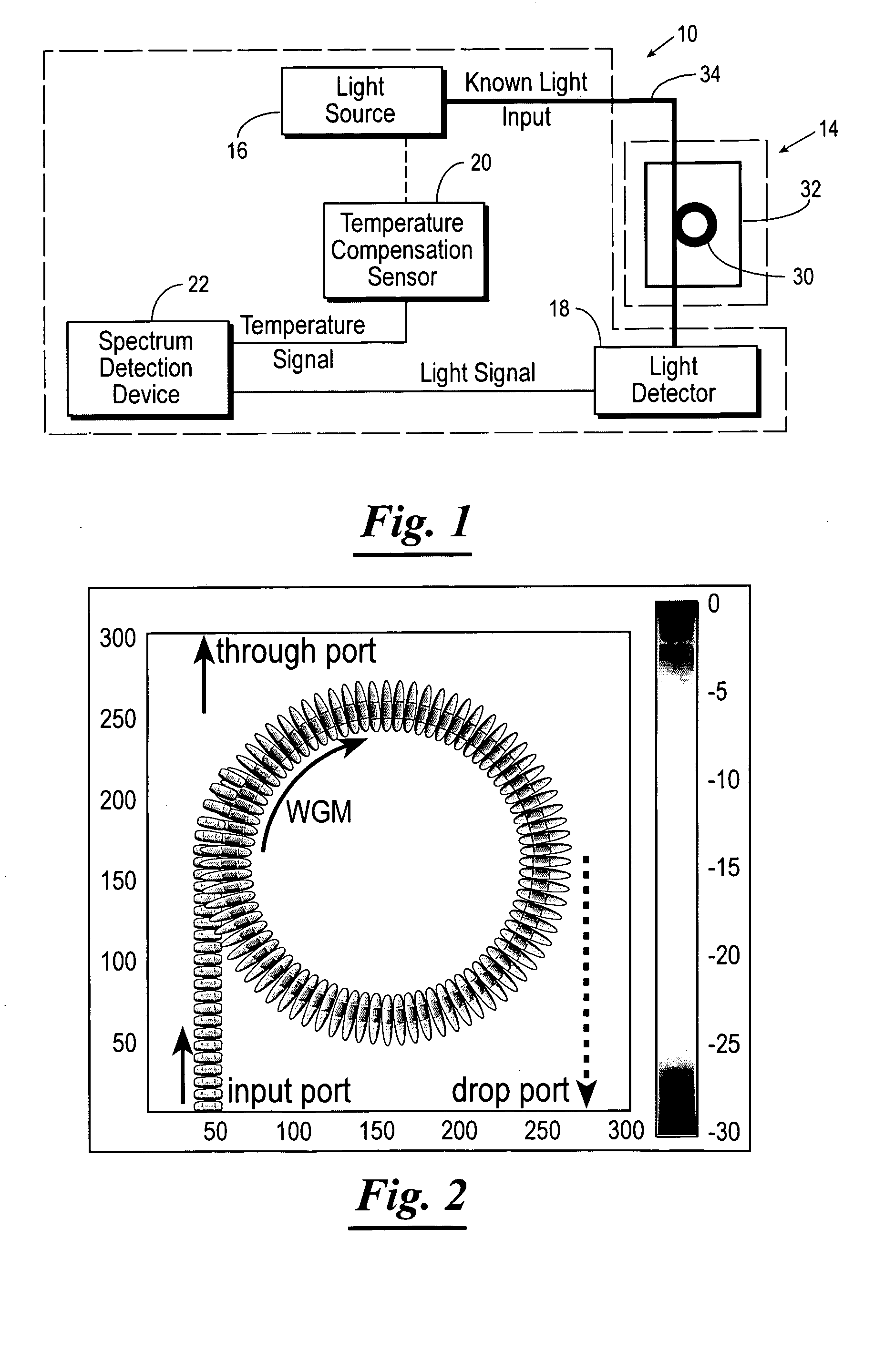
[0039] Referring now to the drawings, and in particular to FIG. 1, shown therein and designated by a reference numeral 10 is an optically-powered integrated microstructure pressure sensing system for sensing pressure within a vessel 12, such as a flow-line or tank. The optically-powered integrated microstructure pressure sensing system 10 will be referred to hereinafter as the “pressure sensing system”. An example of the vessel 12 is depicted in FIG. 7. In general, the pressure sensing system 10 is provided with one or more pressure sensor 14, one or more light source 16, one or more light detector 18, one or more temperature compensation sensor 20, and one or more spectrum detection device 22.

[0040] The pressure sensor 14 is provided with one or more optical resonant structure 30, one or more substrate 32, one or more input optical pathway 34, and one or more output optical pathway 36. The optical resonant structure 30 is subject to the pressure within the vessel 12 and has physic...


PUM

PropertyMeasurementUnit
pressuresaaaaaaaaaa
pressureaaaaaaaaaa
diameteraaaaaaaaaa

Abstract

An optically-powered integrated microstructure pressure sensing system for sensing pressure within a cavity. the pressure sensing system comprises a pressure sensor having an optical resonant structure subject to the pressure within the cavity and having physical properties changing due to changing pressures within the cavity. A substrate supports the optical resonant structure. An input optical pathway evanescently couples light into the optical resonant structure. An output optical pathway collects light from the optical resonance structure. A light source delivers a known light input into the input optical pathway whereby the known light input is evanescently coupled into the optical resonant structure by the input optical pathway and a portion of such light is collected from the optical resonant structure by the output optical pathway. A light detector receives the portion of the light collected from the optical resonant structure, and generates a light signal indicative of such portion of the light collected from the optical resonant structure. A temperature compensation sensor generates a temperature signal indicative of the temperature near the optical resonant structure. A spectrum detection device receives the light signal and temperature signal. The spectrum detection device analyzing the light signal and the temperature signal with a detection algorithm to generating a pressure signal indicative of the pressure within the cavity.

Description

CROSS-REFERENCE TO RELATED APPLICATIONS [0001] The present patent application claims priority to the provisional patent application identified by U.S. Ser. No. 60 / 548,046 filed on Feb. 26, 2004, the entire content of which is hereby incorporated herein by reference.STATEMENT REGARDING FEDERALLY SPONSORED RESEARCH AND DEVELOPMENT [0002] The present invention was supported by National Institute of Science and Technology (NIST) Small Business Innovation Research (SBIR) program, SB1341-04-W-1128. BACKGROUND OF THE INVENTION [0003] High-pressure transducers play several important roles in a variety of industries. The most demanding application for precision high-pressure transducers may be found in the oil and gas production industry. The oil and gas production capacity of a reservoir is determined from models using the precision measurement of pressure during and after product is vented through a standard orifice. Monitors for reservoir pressure operate in a “downhole” environment with ...

Claims


Application Information

Patent Timeline
Patent Type & Authority Applications(United States)
IPC IPC(8): C03B37/07G01L11/02
CPCG01L11/02
Inventor JA, SHIOU-JYHSALSMAN, LLOYDSTRECKER, BRIANSHELTON, ROBERT
Owner FLIR DETECTION
Why Eureka
Try Eureka