Air/oil separation system and method

Active Publication Date: 2005-09-29
PRATT & WHITNEY CANADA CORP
View PDF21 Cites 86 Cited by
  • Summary
  • Abstract
  • Description
  • Claims
  • Application Information

AI Technical Summary

Benefits of technology

[0006] The air/oil separation system of the present invention advantageously reduces heat transfer to, for example, an accessories gearbox (AGB) in which the air/oil separating system is installed and operated, because the structure of the air/oil separating system of the present invention permits the hot air/oil mixture to be collected directly from the m

Problems solved by technology

However, the air/oil mixture collected from the main bearing cavities of the aircraft engine is relatively hot and the temperature thereof i

Method used


Image

  • Air/oil separation system and method
  • Air/oil separation system and method
  • Air/oil separation system and method

Examples


Embodiment Construction

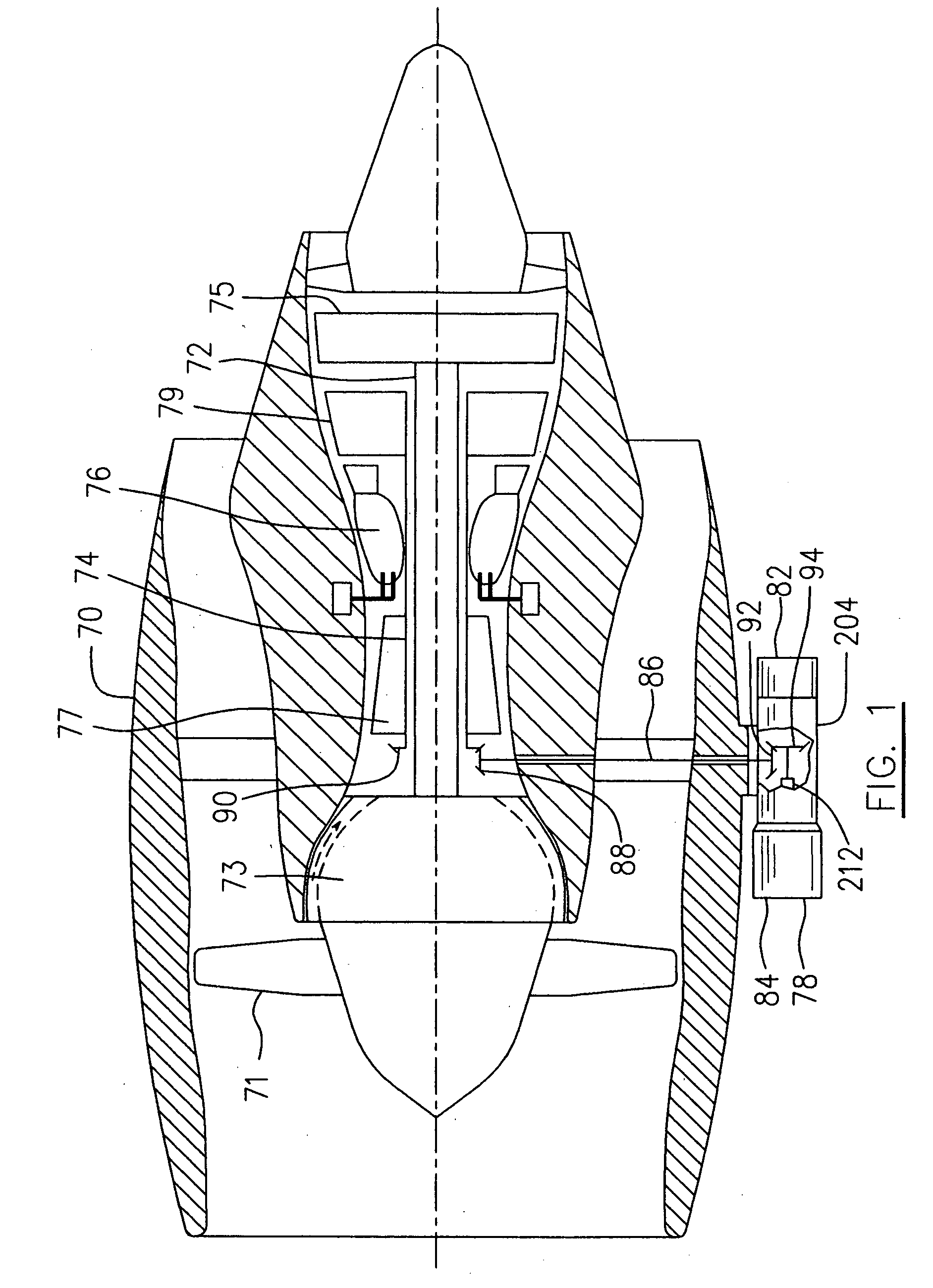
[0013] A bypass gas turbine engine seen schematically in FIG. 1 which incorporates an embodiment of the present invention to illustrate as an example, the application of the present invention, includes a housing or nacelle 70, a low pressure spool assembly seen generally at 72 which includes a fan 71, low pressure compressor 73 and low pressure turbine 75, a high pressure spool assembly seen generally at 74 which includes a high pressure compressor 77, high pressure turbine 79 and a bevel gear 90, a burner seen generally at 76, and an accessory drive assembly seen generally at 78.

[0014] Accessory drive assembly 78 includes, for example, a gearbox 204 secured to a bottom mounting face of nacelle 70, a pump assembly 82 secured to an aft mounting face of gearbox 204 and a starter generator 84 secured to a forward mounting face of gearbox 204. Accessory drive assembly 78 is driven by high pressure spool 74 via an accessory shaft 86 carrying a bevel gear 88 at its upper end engaging bev...


PUM

PropertyMeasurementUnit
Centrifugal forceaaaaaaaaaa

Abstract

A centrifugal air/oil separation system communicates with bearing cavities of the engine and substantially isolates separated oil from contacting the gearbox.

Description

FIELD OF THE INVENTION [0001] The present invention relates to an air / oil separation system and a method of lubricating an aircraft engine using same. BACKGROUND OF THE INVENTION [0002] The air / oil separator described in U.S. Pat. No. 6,398,833, to Santerre et al. and assigned commonly herewith has a rotatable hollow shaft to which the air / oil separator is mounted. The air / oil mixture is collected from the main bearing cavities and delivered to the accessories gearbox (AGB) casing, before entering the air / oil separator. However, the air / oil mixture collected from the main bearing cavities of the aircraft engine is relatively hot and the temperature thereof is typically more than 400 degrees F. Heat reduces the longevity of the seals of the AGB, however, therefore, there is a need for improvement. SUMMARY OF THE INVENTION [0003] An object of the present invention is to provide an improved air / oil separating system. [0004] In accordance with one aspect of the present invention, there ...

Claims


Application Information

Patent Timeline
IPC IPC(8): B01D45/12B01D46/14B04B5/08F01D25/18F01M11/02F02C7/06F16N33/00
CPCB01D50/002F01D25/125F05D2240/70F01D25/20Y02T50/675F01D25/18B01D50/20Y02T50/60
Inventor LATULIPE, ERICSANTERRE, RICHARD
Owner PRATT & WHITNEY CANADA CORP
Why Eureka
Try Eureka