Work vehicle

Active Publication Date: 2005-09-29
KUBOTA LTD
View PDF22 Cites 30 Cited by
  • Summary
  • Abstract
  • Description
  • Claims
  • Application Information

AI Technical Summary

Benefits of technology

[0006] In view of the above-described problem of the convention, a primary object of the present invention is to provide

Problems solved by technology

This tends to result in clogging of the air vent holes of the side faces of the hood with various foreign objects such as grass, bugs, etc., As a result, there occu

Method used


Image

  • Work vehicle
  • Work vehicle
  • Work vehicle

Examples


Example

[First Embodiment]

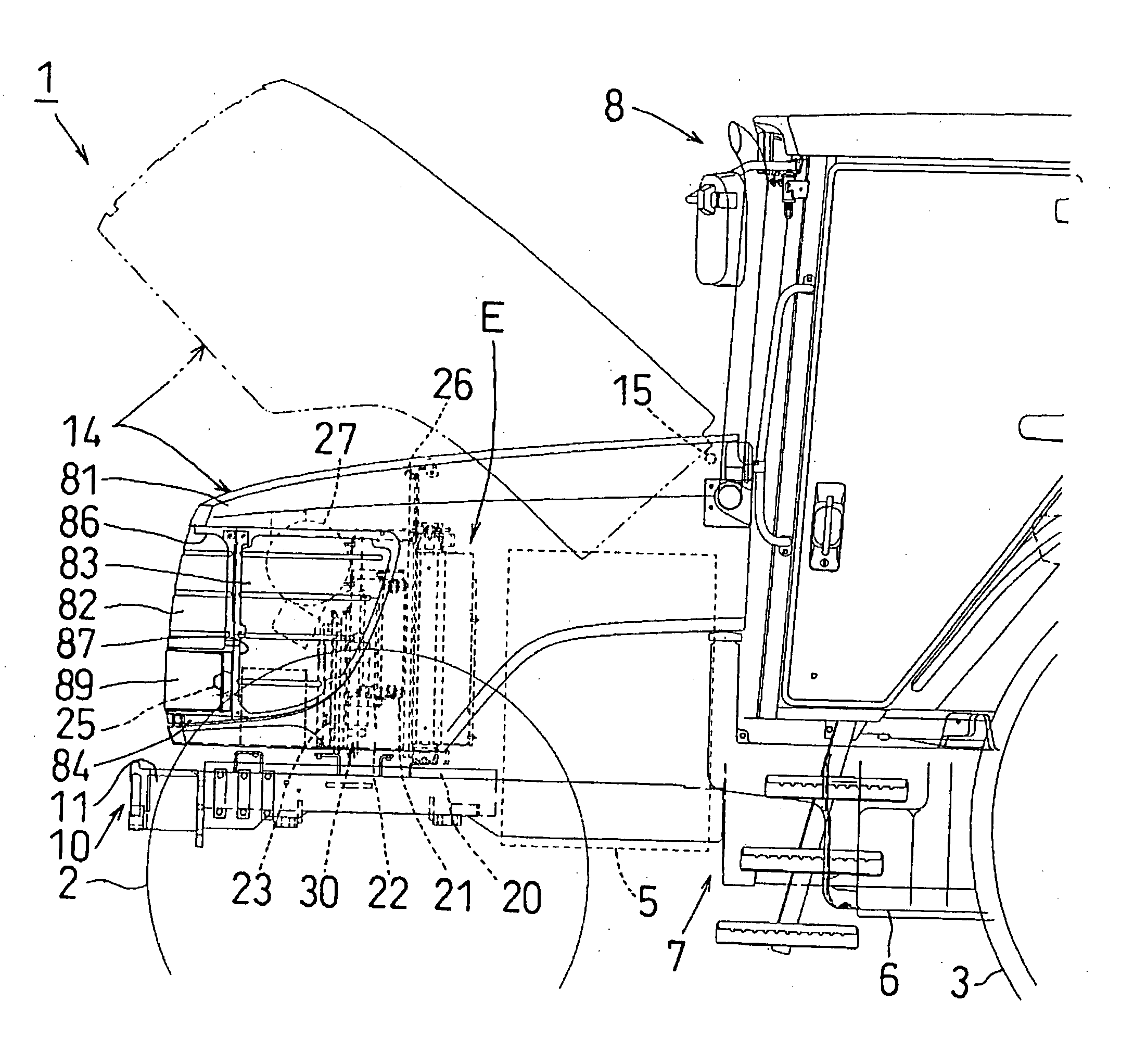
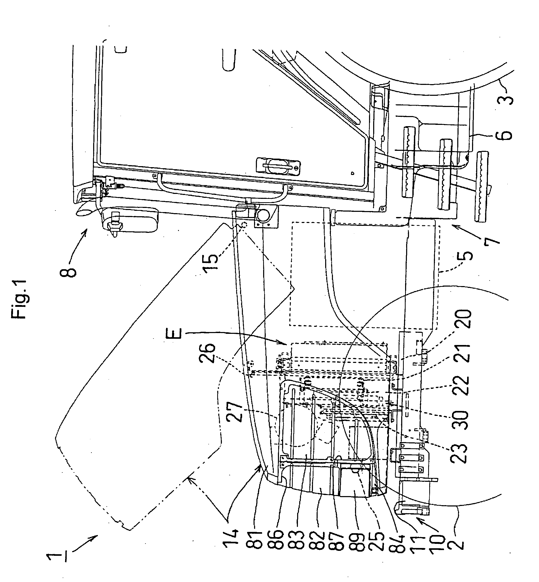
[0057] In FIG. 1, a tractor 1, as an example of work vehicle, includes a pair of right and left front wheels 2 used for steering and auxiliary traveling drive, and a pair of right and left rear wheels 3 used for main traveling drive. The tractor 1 is driven by a drive force transmitted from an engine 5. Further, this tractor 1 can be switched over between a two-wheel drive mode (rear wheel drive) and four-wheel drive mode (front and rear wheels drive) by means of switching means. The engine 5, a transmission case 6 etc. together constitute a traveling vehicle body 7, which mounts, at a rear portion thereof, an independent mount type cabin 8 including a driver's seat and a driving section.

[0058] The traveling vehicle body 7 mounts, at a front portion thereof, the engine 5 and a front axle frame 10 supporting axles of the right and left front wheels 2. An upper portion of the front axle frame 10 is covered with a hood 14 formed of a metal plate or resin shaped like...

Example

[Second Embodiment]

[0108] The side faces of the hood 14 can be alternatively constructed as shown in FIG. 24.

[0109] In the first embodiment, the size of the air vent holes is set same for the right and left side faces and the front face of the hood 14 and the disposing density (the number of air vent holes per unit area) is set smaller for the air vent holes 102 of the side faces of the hood 14 than the air vent holes 101 of the front face of the hood 14 and the air vent holes 101 of the front lower end of the hood 14.

[0110] Instead, as shown in FIG. 24, in this second embodiment, the air vent holes 102 of the side faces of the hood 14 are smaller than the air vent holes 101 of the front face of the hood 14 and the air vent holes 101 of the front lower end of the hood 14. With this, the ratio of the air vent holes relative to the air vent hole forming area is smaller for the side faces of the hood 14 than for the front face thereof.

[0111] In this second embodiment, as shown in F...

Example

[Third Embodiment]

[0113] Further, as shown in FIG. 25, in this embodiment, the disposing pitch (the number of air vent holes per unit area) of the air vent holes 102 of the side faces of the hood 14 is set smaller than the disposing pitch of the air vent holes 101 of the front face of the hood 14 and also the disposing pitch of the air vent holes 101 of the front lower end of the hood 14. In addition, the air vent holes 102 of the side faces of the hood 14 are smaller than the air vent holes 101 of the front face of the hood 14 and the air vent holes 101 of the front lower end of the hood 14. With this, the velocities of the introduced ambient air from the right and left faces and the front face of the hood 14 are equated with each other.

[0114] In this third embodiment, as shown in FIG. 25 for example, the air vent holes 102 (corresponding to the second air vent holes) of the side grill member 83 are formed as round holes with a diameter of 0.75 mm, which is a half of the diameter...


PUM


Abstract

A work vehicle includes a traveling vehicle body and a hood provided at a front portion of the vehicle body for covering an engine room. The hood includes a front face having a plurality of first air vent holes and right and left side faces each having a plurality of second air vent holes. A radiator is mounted inside the hood, ambient air being drawn in through the first and second air vent holes toward the radiator. A vent hole area ratio of each side face of the hood determined by the second air vent holes is set smaller than a vent hole area ratio of the front face of the hood determined by the first air vent holes.

Description

BACKGROUND OF THE INVENTION [0001] 1. Field of the Invention [0002] The present invention relates to a work vehicle such as an agricultural tractor, more particularly to a work vehicle having a hood provided at a front portion of a vehicle body for covering an engine room. [0003] 2. Description of the Related Art [0004] With some work vehicles such as tractors, a radiator is provided inside a hood and this hood includes a number of air vent holes in its right and left side faces and its front face, so that ambient air may be introduced from the right and left side faces and the front face toward the radiator. In the case of a conventional hood construction of this type, a vent hole area ratio (a ratio of vent forming area relative to a unit area of the total air vent hole forming portion) is fixedly set the same for each side face and the front face of the hood. That is, air vent holes of a same size are formed in the right and left side faces and the front face of the hood and also...

Claims


Application Information

Patent Timeline
IPC IPC(8): B60K11/08B60K11/06B62D25/10B62D49/06
CPCB60K11/08B62D49/06B62D25/10B60Y2200/221F01P2070/52
Inventor OBE, MITSUHIKOASADA, AKIHIROKOBAYASHI, TAKASHI
Owner KUBOTA LTD
Why Eureka
Try Eureka