Linear actuator

Inactive Publication Date: 2005-09-29
SHINANO KENSHI
View PDF8 Cites 15 Cited by
  • Summary
  • Abstract
  • Description
  • Claims
  • Application Information

AI Technical Summary

Benefits of technology

[0018] By using the linear actuator described above, the yoke components that construct the yoke part are combined on the outer circumference of a guide pipe e.g., with facing end surfaces of the first yokes in contact, facing end surfaces of the second yokes in contact, facing end surfaces of the first yokes and facing end surfaces of the second yokes in contact, or the facing end surfaces of the first yokes in close proximity. As a result, there is no gap between the facing end surfaces of the first yokes and second yokes, or even if gaps do exist, such gaps can be made as small as possible. Accordingly, leak magnetic flux from the facing yoke end surfaces and/or the proximate yoke end surfaces can be greatly reduced, so that the magnetic flux acts having been concentrated on the outer circumferential surfaces of the first yokes. Therefore, by using a small permanent magnet with high coercive force and a high operating point, it is possible to improve the output performance while miniaturizing the yoke part. Also, since it is possible to increase the interlinking magnetic flux perpendicular to the direction in which the current flows through the coil, ineffective components that reduce the thrust of the moving part (the yoke part or the shaft-linked part) are reduced, vibration in the radial direction does not occur and the magnetic flux that is produced from the permanent magnets can be effectively converted into thrust that acts upon the moving part in the axial direction, thereby improving the output performance.
[0019] Also, since the yoke components are combined on the outer circumference of the guide pipe with the first yokes facing one another, it is possible to coaxially combine the yoke components with a shaft hole diameter of the respective yoke components or the outer circumference of the guide pipe as a reference position, so that coaxial alignment of the yoke part is easy to achieve. This makes assembly easier and improves the assembly precision. Accordingly, even if the internal space of the yoke part is narrowed, interference will not occur between the shaft-linked part and the yoke part, thereby improving the operational stability of the linear actuator.
[0020] Also, by coaxially positioning the components by stacking the first yoke on one side of the permanent magnet and the second yoke on the other side an

Problems solved by technology

However, if the gap between the pole shoes 52 and the tubular yoke 54 is increased, the leak magnetic flux from the magnetic circuits increases, so that a large thrust cannot be produced in the moving part in the axial direction.
However, to reliably harde

Method used


Image

  • Linear actuator
  • Linear actuator
  • Linear actuator

Examples


Example

First Embodiment

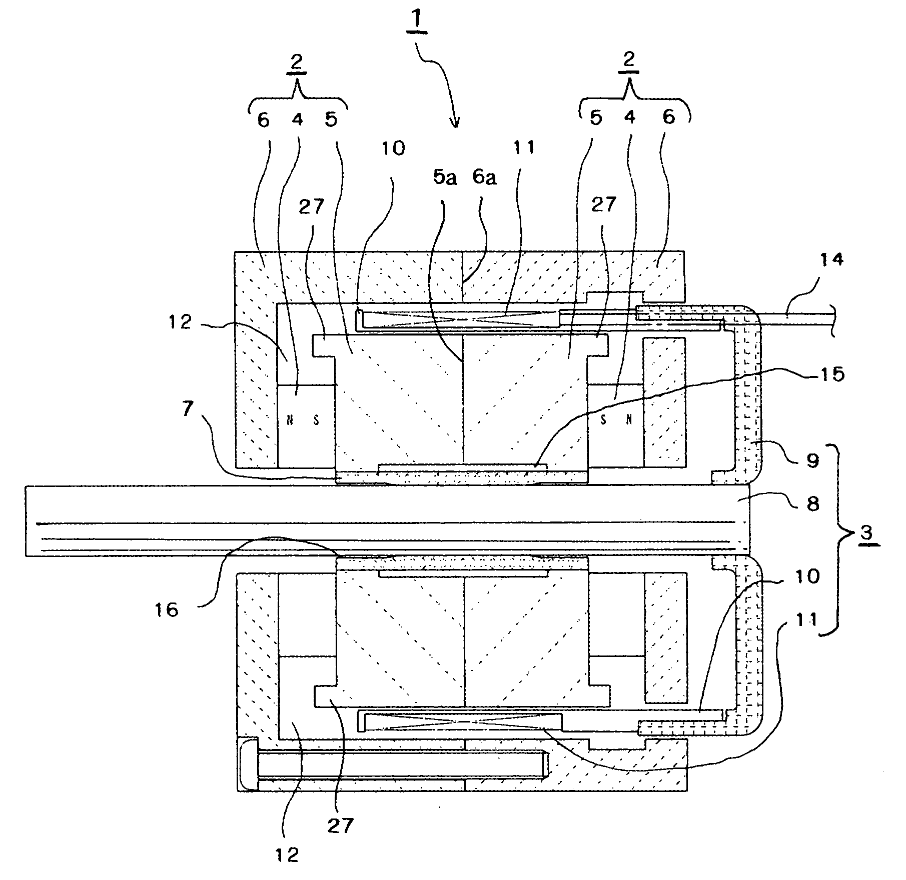
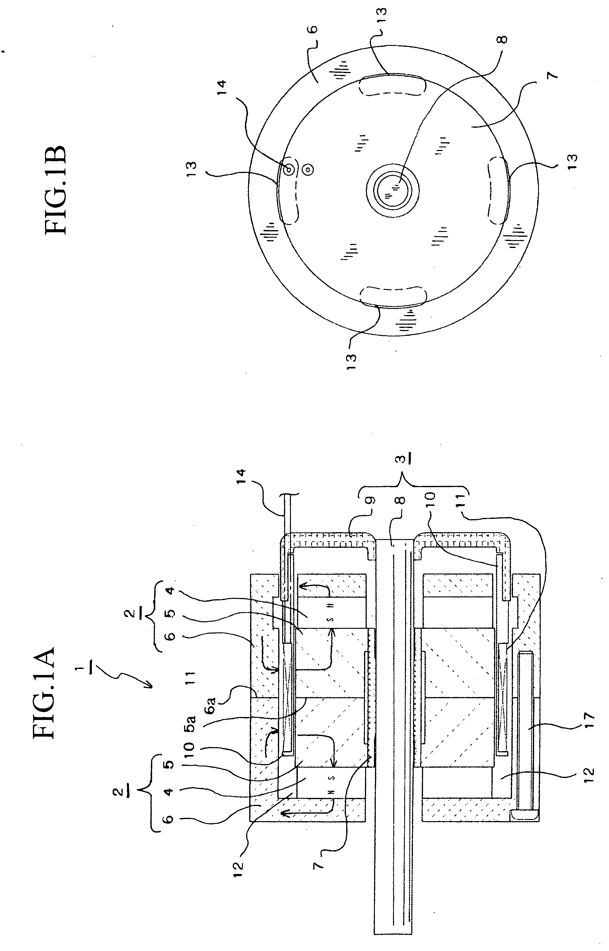
[0042] The overall construction of a linear actuator according to a first embodiment will now be described with reference to FIGS. 1A to FIG. 6. In FIG. 1A, the yoke part (fixed part) 1 is formed by combining left and right yoke components 2, and a shaft-linked part (moving part) 3 is provided in spaces inside and outside the yoke part 1 and at a shaft core of the yoke part 1. In each yoke component 2, a ring-shaped first yoke 5 is provided adjacent to one side of a ring-shaped permanent magnet 4 and a cup-shaped second yoke 6 is provided adjacent to the other side of the permanent magnet 4. The first yoke 5 and the second yoke 6 are integrally attached to the permanent magnet 4 using adhesive. As examples, a neodymium magnet made of a neodymium-iron-boron (Ne—Fe—B) alloy or an alnico magnet made of an aluminum-nickel-cobalt (Al—Ni—Co) alloy, and the like can be used as the permanent magnet 4.

[0043] The yoke part 1 is formed by attaching the respective yoke compone...

Example

Second Embodiment

[0058] Next, another embodiment of a linear actuator will be described. Components that are the same as in the first embodiment have been assigned the same numerals and description thereof has been omitted, with the following description focusing on the different constructions.

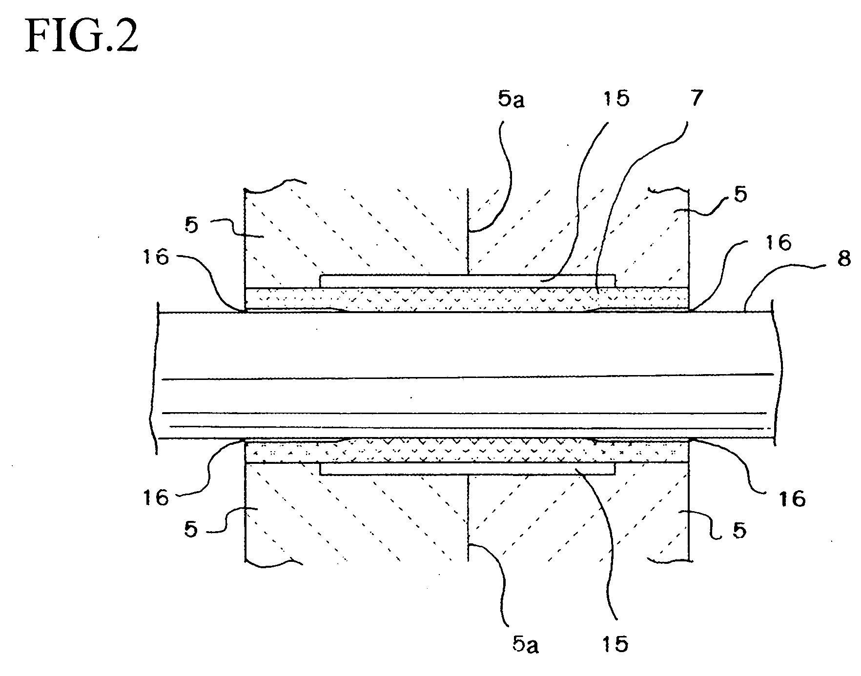
[0059] In FIG. 7, the pressing-in construction for the guide pipe 7 pressed into the shaft hole of the yoke part 1 differs. That is, the positions in the axial direction of the first gap 15 and the second gaps 16 that are formed in the inner circumferential surface side and the outer circumferential surface side of the guide pipe 7 differ. In the present embodiment, the guide pipe 7 is pressed into shaft holes in the second yokes 6 in the left and right yoke components 2. In the guide pipe 7 pressed into the shaft holes of the yoke components 2 (specifically in the second yokes 6 in the present embodiment), the first gap 15 is formed between the outer circumferential surface of the guide pip...

Example

Third Embodiment

[0060] Next, another embodiment of a linear actuator will be described. Components that are the same as in the first embodiment have been assigned the same numerals and description thereof has been omitted, with the following description focusing on the different constructions.

[0061]FIG. 8 shows a different pressing-in construction for the guide pipe 7 pressed into the shaft hole of the yoke part 1. That is, in the present embodiment, the guide pipe 7 is pressed into shaft holes in the first yokes 5 and the second yokes 6 in the left and right yoke components 2. When the guide pipe 7 is pressed into the shaft holes of the yoke components 2 (in the present embodiment, the first yokes 5 and the second yokes 6), the first gap 15 is formed between the outer circumferential surface of the guide pipe 7 and the inner circumferential surfaces of the first yokes 5 corresponding to an area in the axial direction including a position where the pipe inner circumferential surfa...


PUM


Abstract

A linear actuator has improved output performance and can be assembled with high precision. The linear actuator includes: a yoke part where yoke components, where a hollow is formed between an outer circumferential surface of a first yoke provided on one side of a ring-shaped permanent magnet and an inner circumferential surface of a second yoke provided on another side of the ring-shaped permanent magnet, are combined on an outer circumference of a guide pipe with end surfaces of the first yokes and/or end surfaces of the second yokes being in contact and magnetic poles formed in facing yoke surfaces having a same polarity; and a shaft-linked part where a coil bobbin, which is disposed in the hollow of the yoke part and around which a coil has been wound, and a shaft inserted into the guide pipe are linked. By switching the direction of the current flowing in the coil, relative movement between the yoke part and the shaft-linked part is reciprocally caused in an axial direction.

Description

BACKGROUND OF THE INVENTION [0001] 1. Field of the Invention [0002] The present invention relates to a voice coil linear actuator and in particular to a small, high-performance linear actuator used in a hydraulic / pneumatic control apparatus or in a precise positioning device such as a hard disk drive. [0003] 2. Related Art [0004] One example of a conventional linear actuator will be described with reference to FIG. 13. As a fixed part, a yoke part 55 is formed by disposing a pair of ring-shaped permanent magnets 51 with the same poles facing one another, disposing a pole shoe 52 on one side of each magnet 51 and a side yoke 53 on the other sides, and disposing a tubular yoke 54 between the respective side yokes 53. As a moving part, a coil support 56 is provided in a hollow 61 provided between the facing pole shoes 52 of the yoke part 55. On the outer circumference of the coil support 56, a coil bobbin 57 is disposed in a gap 62 between the circumferential surfaces of the pole shoes...

Claims


Application Information

Patent Timeline
IPC IPC(8): H02K41/00H02K33/18H02K41/035
CPCH02K41/0356
Inventor OKUBO, MASASHI
Owner SHINANO KENSHI
Why Eureka
Try Eureka