Plasma display panel

a technology of display panel and plasma, which is applied in the field of plasma display panel, can solve the problems of low discharge efficiency of conventional pdp and inefficiency of second dielectric layer b>19/b>, and achieve the effect of improving discharge efficiency

Inactive Publication Date: 2005-09-29
SAMSUNG SDI CO LTD
View PDF15 Cites 35 Cited by
  • Summary
  • Abstract
  • Description
  • Claims
  • Application Information

AI Technical Summary

Benefits of technology

[0018] The present invention provides a

Problems solved by technology

A conventional PDP may have low discharge efficiency due to a short sustain discharge path and because the discharge ma

Method used


Image

  • Plasma display panel
  • Plasma display panel
  • Plasma display panel

Examples


Embodiment Construction

[0041] The following describes exemplary embodiments of the present invention with reference to the accompanying drawings.

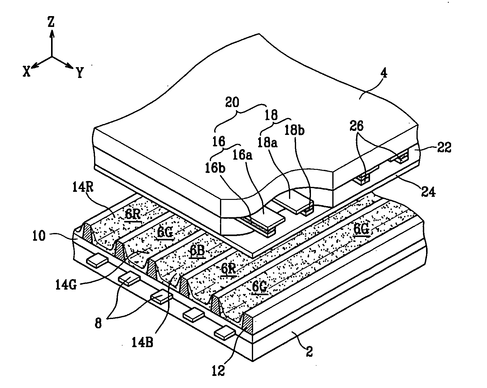
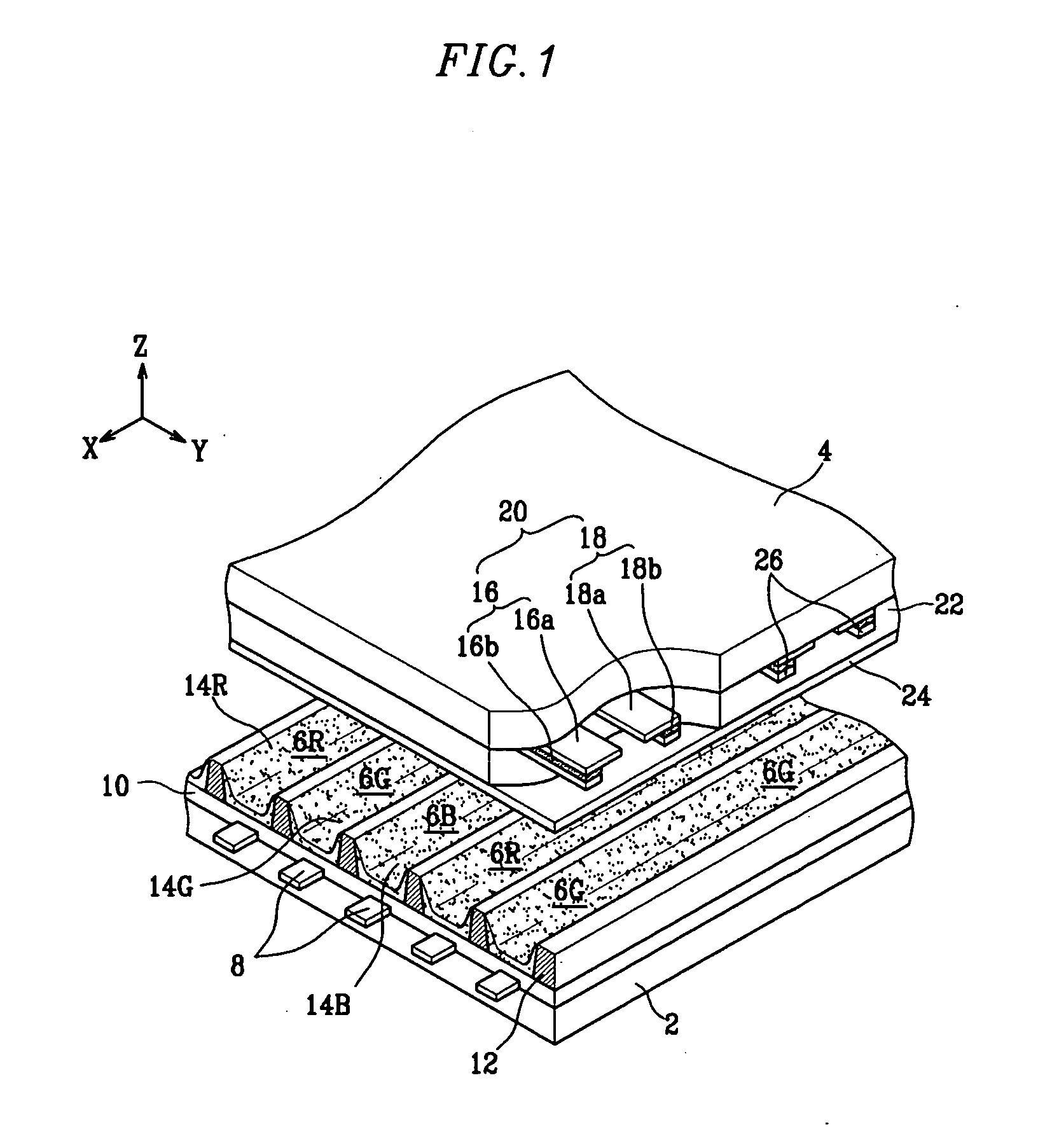
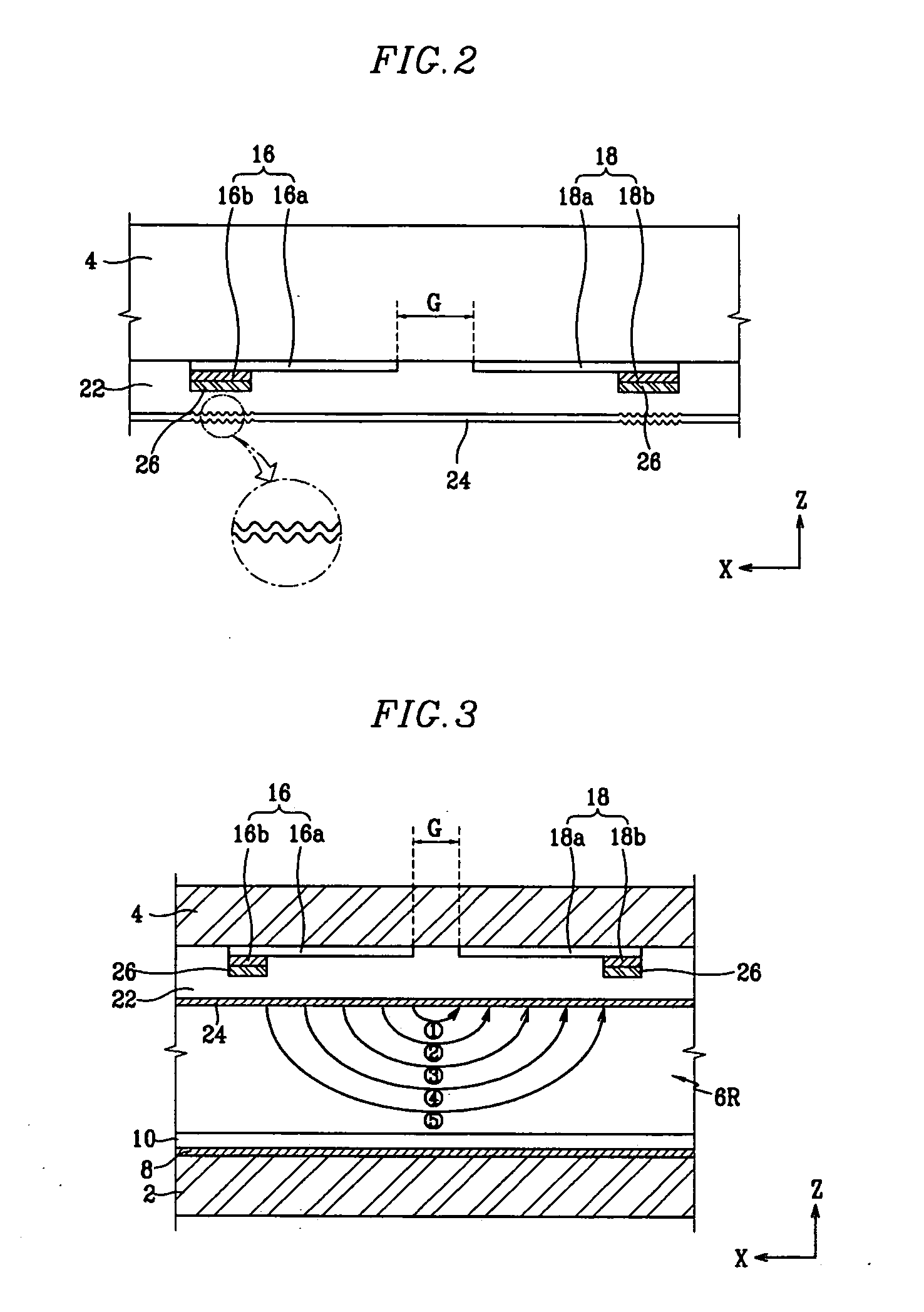
[0042]FIG. 1 is a partial exploded perspective view of a PDP according to the present invention, and FIG. 2 is a partial sectional view of a second substrate shown in FIG. 1.

[0043] As shown in FIG. 1 and FIG. 2, a first substrate 2 faces a second substrate 4 and is separated from it by a predetermined distance. The first and second substrates 2, 4 have discharge cells 6R, 6G, 6B therebetween. The discharge cells 6R, 6G, 6B emit visible rays, according to an independent discharge mechanism, to realize color images.

[0044] More specifically, a plurality of address electrodes 8, which are covered by a first dielectric layer 10, are formed on the first substrate 2 in one direction (in the direction of the X axis of FIG. 1). The address electrodes 8 may be arranged in patterns such as a striped pattern.

[0045] Barrier ribs 12 may be arranged on the first dielectric ...


PUM


Abstract

A plasma display panel with reinforcing electrodes arranged at both ends of discharge cells along a direction address electrodes are formed and coupled to display electrodes. The reinforcing electrodes may comprise carbon-based material such as carbon nanotubes or graphite, and they may be stacked in two or more layers and covered with a dielectric layer and a protective layer. The dielectric layer may be interposed between the reinforcing electrodes and the display electrodes. The dielectric layer may expose the reinforcing electrodes so that the protective layer covers the reinforcing electrodes. A portion of the protective layer corresponding to the reinforcing electrodes has a surface roughness of about 300 nm to about 700 nm.

Description

CROSS REFERENCE TO RELATED APPLICATION [0001] This application claims priority to and the benefit of Korean Patent Application No. 10-2003-0086131, filed on Nov. 29, 2003, which is hereby incorporated by reference for all purposes as if fully set forth herein. BACKGROUND OF THE INVENTION [0002] 1. Field of the Invention [0003] The present invention relates to a plasma display panel (PDP). More specifically, the present invention relates to a PDP having enhanced discharge efficiency. [0004] 2. Discussion of the Related Art [0005] Flat panel display devices, including liquid crystal displays (LCDs), field emission displays (FEDs), PDPs, and organic electroluminescence display devices, have been recently developed to improve upon the larger and heavier cathode ray tubes (CRT). [0006] Among these flat panel display devices, large PDPs, which display characters or images using plasma generated by gas discharge, may be easily manufactured. A typical three-electrode surface discharge alter...

Claims


Application Information

Patent Timeline
IPC IPC(8): H01J17/04H01J17/49
CPCB82Y10/00H01J11/12H01J2211/245H01J11/30H01J11/24H01J11/38
Inventor AHN, JEONG-CHULLSON, SEUNG-HYUN
Owner SAMSUNG SDI CO LTD
Why Eureka
Try Eureka