Circuit protection device with timed negative half-cycle self test
a circuit protection device and half-cycle self-test technology, applied in emergency protective circuit arrangements, testing circuits, instruments, etc., can solve problems such as ground fault, low power arc between the two conductors, and arc faul
- Summary
- Abstract
- Description
- Claims
- Application Information
AI Technical Summary
Benefits of technology
Problems solved by technology
Method used
Image
Examples
second embodiment
[0061] As embodied herein and depicted in FIG. 11, a schematic of a circuit protection device 10 in accordance with the present invention is disclosed. This embodiment differs from the embodiments depicted in FIGS. 1-10 by the addition of control gate 1116, by-pass circuit 1126, and several alternative routes for the ring detector 400 output.
[0062] Control gate 1116 is coupled to detector 16 and configured to receive either detector output signal 1120 or filtered detector output signal 20. Control gate 1116 gates these signals and provides a gated and delayed detection signal to SCR 24 (SCR out). Control gate 1116 is configured to recycle between a test state and a non-test state. The durations of each of the two states are established by a timing circuit. Those of ordinary skill in the art will recognize that the timing circuit may be of any suitable type. For example, the timing circuit may be an external clocking arrangement driven by a local oscillator (not shown), a timer dispo...
third embodiment
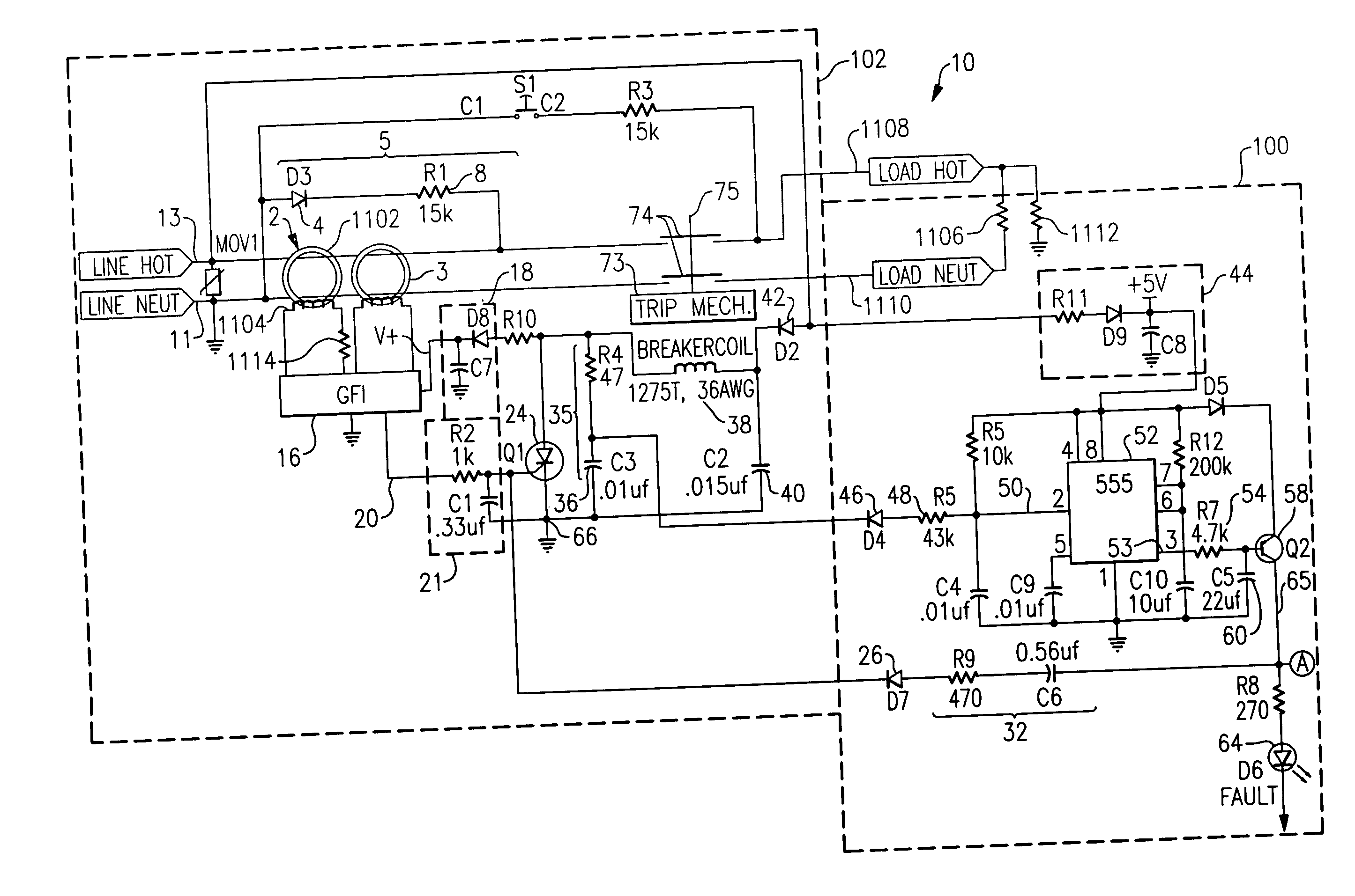
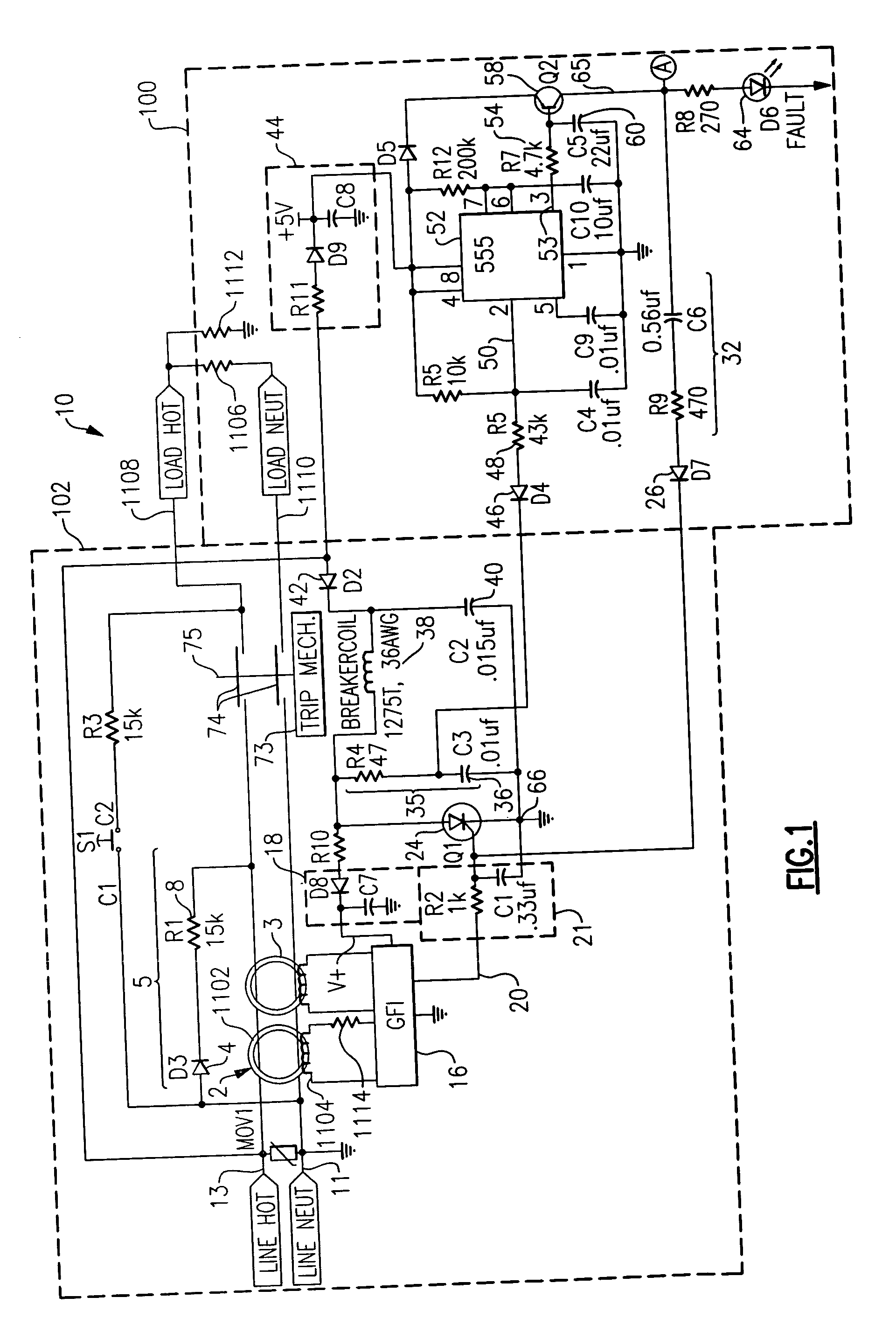
[0075] As embodied herein and depicted in FIG. 12, a schematic of a circuit protection device in accordance with the present invention is disclosed. FIG. 12 is a schematic diagram of an alternate embodiment in which the fault simulation circuit generates a simulated negative half cycle grounded neutral signal. Reference is made to U.S. patent application Ser. No. 10 / 768,530, which is incorporated herein by reference as though fully set forth in its entirety, for a more detailed explanation of the fault simulation signal. Note that test circuit 1128 does not include diode 4.
[0076] The GFI circuit 102 in FIG. 12 includes a transformer 2 that is configured to sense a load-side ground fault when there is a difference in current between the hot and neutral conductors. Transformer 2 sends sensed signal to detector circuit 16. GFI circuit 102 also includes a grounded neutral transmitter 3 that is configured to detect grounded neutral conditions. Those skilled in the art understand that the...
PUM
 Abstract
Description
Claims
Application Information
 - R&D
- Intellectual Property
- Life Sciences
- Materials
- Tech Scout
- Unparalleled Data Quality
- Higher Quality Content
- 60% Fewer Hallucinations
Browse by: Latest US Patents, China's latest patents, Technical Efficacy Thesaurus, Application Domain, Technology Topic, Popular Technical Reports.
© 2025 PatSnap. All rights reserved.Legal|Privacy policy|Modern Slavery Act Transparency Statement|Sitemap|About US| Contact US: help@patsnap.com


