Image exposure device

a technology of exposure device and image, which is applied in the direction of photomechanical equipment, instruments, printing, etc., can solve the problems of reducing the sharpness of an exposed image, affecting the alignment of aperture array and other components, and affecting the quality of the exposed image, so as to reduce the size of the device, save weight, and improve the effect of contras

Inactive Publication Date: 2005-09-29
FUJIFILM HLDG CORP +1
View PDF4 Cites 48 Cited by
  • Summary
  • Abstract
  • Description
  • Claims
  • Application Information

AI Technical Summary

Benefits of technology

[0008] The present invention has been made in view of the circumstances described above. Accordingly, it is an object of the present invention to provide an image exposure device that is capable of lessening a reduction in the sharpness of an exposed image due to chattering of a spatial light modulator and stray light. Another object of the invention is to provide an image exposure device which is capable of realizing a high total extinction ratio and ease of alignment.

Problems solved by technology

However, in image exposure devices using a spatial light modulator such as a DMD, when turning each pixel portion of the spatial light modulator ON / OFF, the problem of chattering will arise.
Also, if stray light that originates in a spatial light modulator, or marginal light is produced and reaches a photosensitive material, it can be another cause of the sharpness of an exposed image being reduced in image exposure devices.
However, if stray light is to be removed by only a single aperture array arranged in the stage after the micro lens array, the size of each aperture and the position of the aperture array must be very strictly determined according to the diameter of the imaging components of each light beam collected by the micro lens array, and consequently, alignment of the aperture array and other components becomes extremely difficult.

Method used


Image

  • Image exposure device
  • Image exposure device
  • Image exposure device

Examples


first embodiment

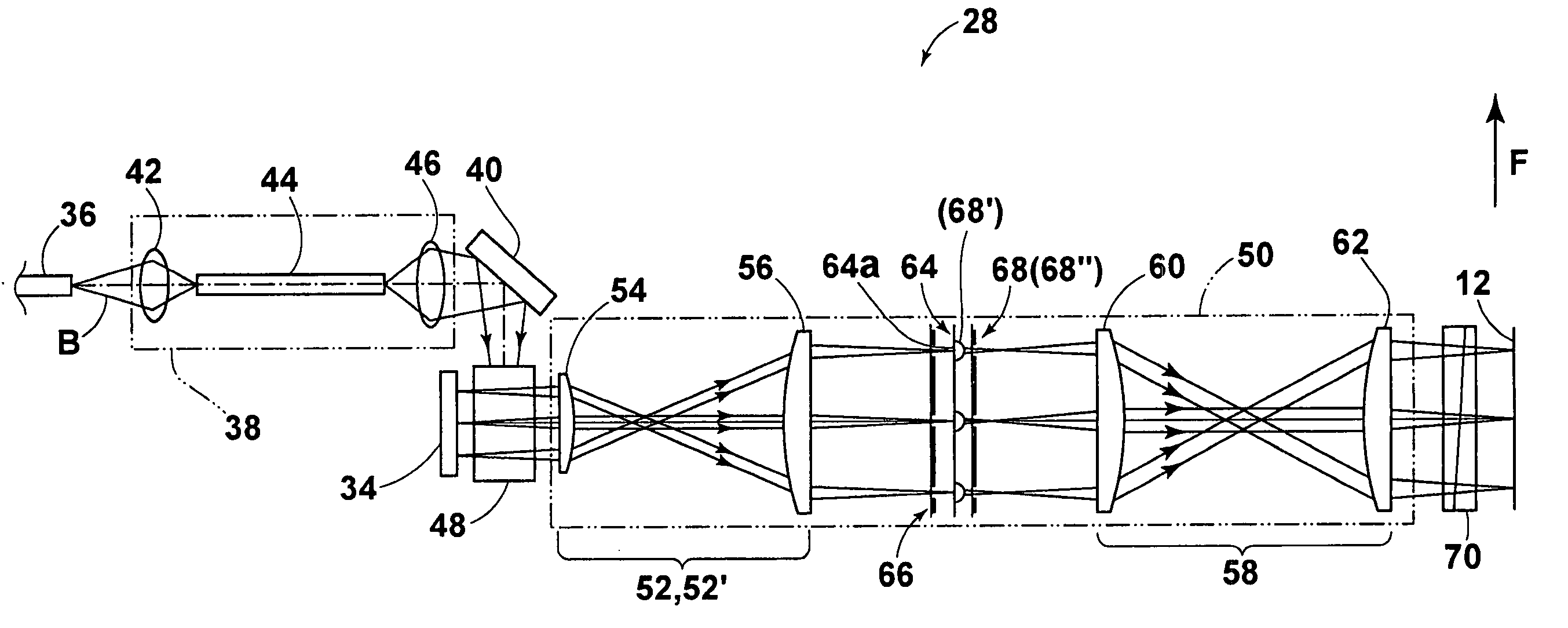
[0095] In the present invention shown in FIG. 15D, a first aperture array 66 is provided in the stage before the micro lens array 64 and a second aperture array 68 is provided in the stage after the micro lens array 64. According to this construction, the stray light component can be removed by the first aperture array 66, and the scattered light component due to the DMD 34 and the marginal light component due to the irregular reflection and multiple reflection in the micro lens array 64 can be reduced by the second aperture array 68. Therefore, removal of stray light and assurance of a high total extinction ratio can be realized at the same time and an exposed image of extremely high sharpness can be obtained on the photosensitive material 12. Furthermore, since the stray light component is removed by the first aperture array 66, the size of each aperture in the second aperture array 68 does not need to make smaller for the purpose of removing stray light. The size of each aperture...

second embodiment

[0101] On the other hand, in the present invention shown in FIG. 18D, a first aperture array 66 is provided in the stage before the micro lens array 64, and a second aperture array 68 is provided in the stage after the micro lens array 64. As shown in the figure, the light components due to chattering can be satisfactorily shut off. In this manner, fluctuations in the position of an exposed point on the photosensitive material 12 can be reduced and high-definition images can be obtained.

[0102] The aforementioned embodiment employs a total of two aperture arrays, first aperture array 66 and second aperture array 68, but may employ three or more aperture arrays.

[0103] From the standpoint of realizing removal of stray light, assurance of a high total extinction ratio, and ease of alignment at the same time, it is also preferable to provide a total of two or more aperture arrays in the stage before the micro lens array and / or the stage after the micro lens array. Even in the case where...


PUM

PropertyMeasurementUnit
focal lengthaaaaaaaaaa
reflectanceaaaaaaaaaa
lengthaaaaaaaaaa

Abstract

An image exposure device includes an exposure head for forming a desired pattern on a photosensitive material. The exposure head is equipped with a light source for emitting a great number of light beams, a spatial light modulator in which a great number of pixel portions are arranged for independently modulating the light beams emitted from the light source, a micro lens array in which a great number of micro lenses are arranged for individually converging the great number of light beams modulated by the pixel portions, and a total of two or more aperture arrays arranged in the stage before the micro lens array and / or the stage after the micro lens array. Each of the aperture arrays has a great number of apertures for individually restricting the light beams.

Description

BACKGROUND OF THE INVENTION [0001] 1. Field of the Invention [0002] The present invention relates to image exposure devices, and more particularly to image exposure devices equipped with an exposure head for forming a desired pattern on a photosensitive material. [0003] 2. Description of the Related Art [0004] There are known image exposure devices with an exposure head for forming a desired pattern on a photosensitive material. This kind of exposure head basically comprises a light source; a spatial light modulator in which a great number of pixel portions are arranged for independently modulating light beams emitted form the light source according to a control signal; and an imaging optics system for forming an image of the light modulated by the spatial light modulator on the photosensitive material. The fundamental construction is described, for example, in A. Ishikawa, “Shortening of Development and Application of Mass Production by Maskless Exposure,” Electronics Mounting Tech...

Claims


Application Information

Patent Timeline
Patent Type & Authority Applications(United States)
IPC IPC(8): B41J2/445G02B26/08G03B27/54G03F7/20
CPCG03B27/54G03F7/2057G03F7/70358G03F7/70275G03F7/70291G03F7/7005
Inventor ISHII, SHUICHIISHIKAWA, HIROMIOKAZAKI, YOJI
Owner FUJIFILM HLDG CORP
Why Eureka
Try Eureka