
Transmission drive line for low level audio analog electrical signals

Inactive Publication Date: 2005-09-29
WALSH WILLIAM J
View PDF6 Cites 5 Cited by
  • Summary
  • Abstract
  • Description
  • Claims
  • Application Information

AI Technical Summary

Benefits of technology

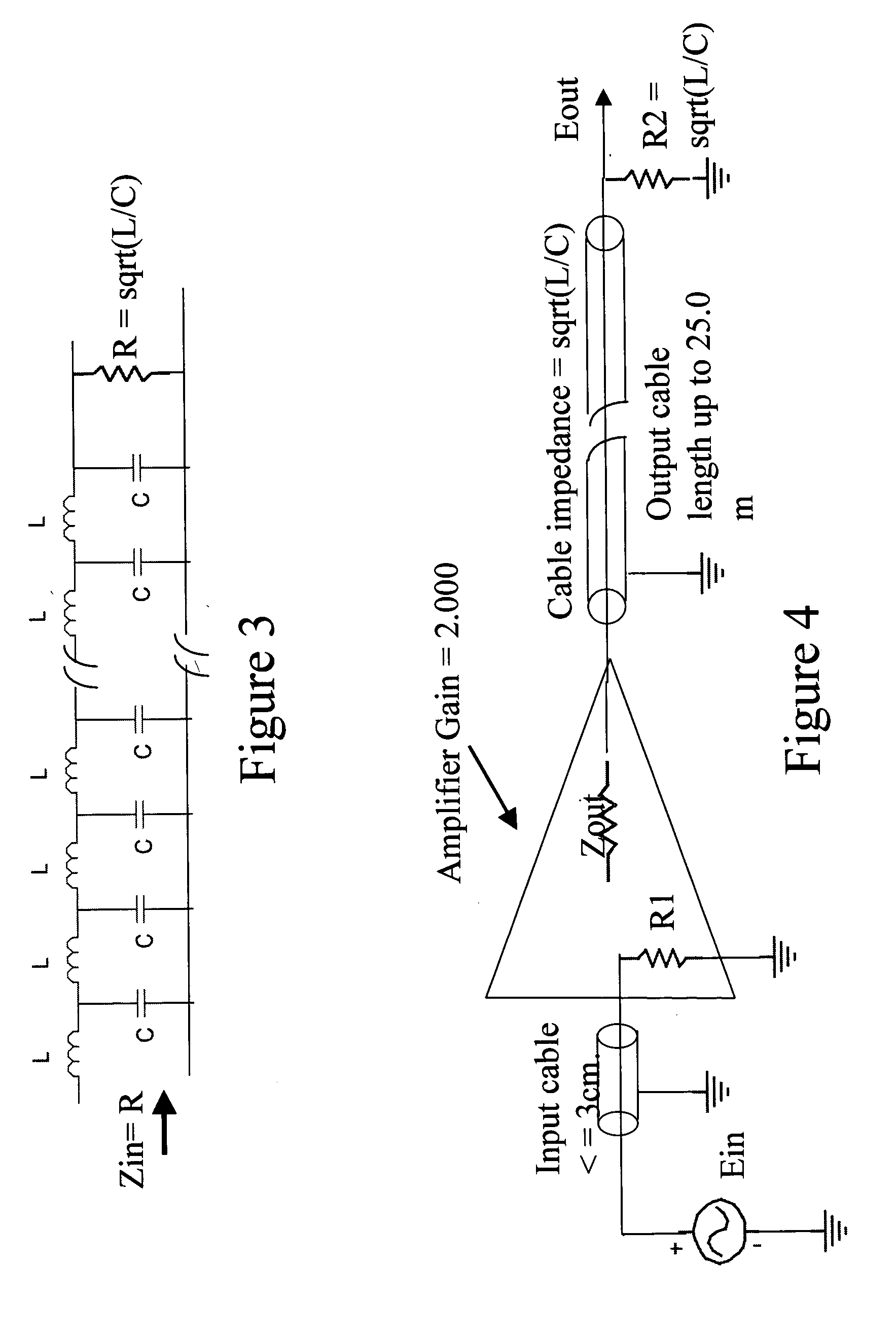
[0011] The objective of the subject invention is to significantly improve the signal fidelity of audio interconnect cables or their “transparency” over the current state of the art. This is accomplished by a unique amplifier circuit that is integral with an interconnect cable that has been terminated in its characteristic impedance. The amplification process is such that the current through the interconnecting cable is increased a thousand times or more while maintaining unity voltage gain of the transmitted signal between sending and receiving ends of the interconnect. The driving amplifier circuit utilizes a dual operational amplifier technique that substantially eliminates “zero cross-over” distortion.

Problems solved by technology

It has long been recognized that each component of an audio system, starting with the signal reproduction source on through the various stages of amplification and finally to the loudspeaker or recording devices, may introduce noise, distortion, bandwidth loss or other forms of signal corruption unless careful precautions are taken in the design, manufacture and use of these audio system components.
But most audiophiles would agree that even the exclusive use of the most carefully engineered components in audio system components, still frequently fails to deliver “live, concert hall realism”.
Thus, many systems were interconnected with little better than ordinary household lamp cord or the equivalent.
These studies have resulted in a general recognition among engineers and audiophiles that in otherwise high quality audio systems the use of ordinary electrical wire for component interconnection noticeably degrades overall system performance.
In particular it is now widely recognized that: 1) All cables have an unavoidable leakage capacitance that increases in direct proportion to their length.
Under certain other conditions high frequency signals from radio transmissions and computer systems also cause signal corruption.
Because of this extremely wide dynamic sensitivity any even slightly noise corrupted, or “rolled-off” electrical signal interferes with listener enjoyment when converted to an audio signal.
However, as will be discussed further in succeeding paragraphs even in the best noise protected cables audiophiles find tonal variations introduced by these cables that undesirably “color” the music and its stereophonic realism.
Unfortunately, however, it is generally agreed among audiophiles that such coaxial cables suffer from an audible clarity defect known in the art as poor “sound-staging”.

Method used


Image

  • Transmission drive line for low level audio analog electrical signals
  • Transmission drive line for low level audio analog electrical signals
  • Transmission drive line for low level audio analog electrical signals

Examples


Embodiment Construction

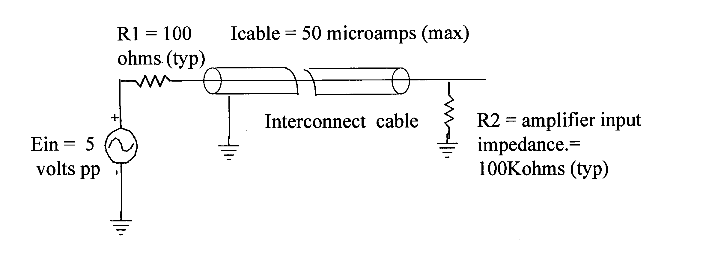
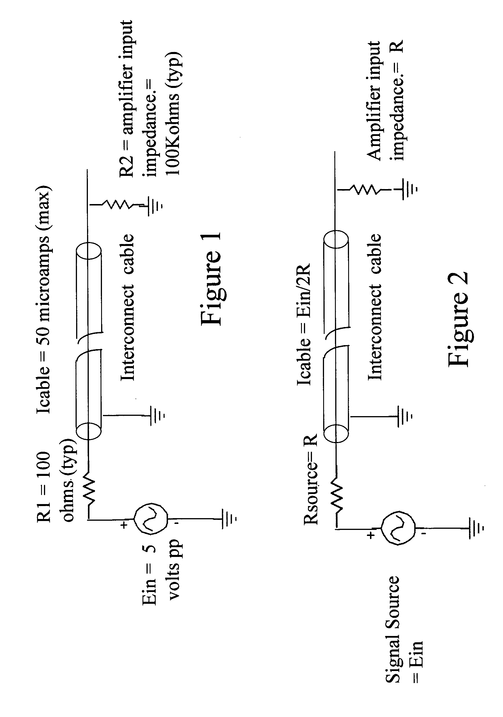
[0020] The basic idea underlying the subject invention stems from the recognition that the typical maximum signal amplitude from an audio source, say a tuner or CD player is of the order of five volts or less with such signal sources having an output impedance typically in the range of hundreds of ohms. Moreover, the input impedance of the receiving unit such as a pre-amplifier or amplifier is of the order of 100,000 ohms or greater. As FIG. 1 illustrates, under these conditions the signal current through the interconnecting cable is limited to the order of 50 microamperes or less. This is to be contrasted with the current, which flows from the output of a typical amplifier to a loud speaker with a power capability of 100 watts or more. In this latter situation the signal current flowing through the connecting cable can be as much as five amperes or more.

[0021] After much experimentation, the inventor has found that a dramatically improved, “concert-hall realism” in audio listening...


PUM


Abstract

An electronically-enhanced cable of known characteristic impedance that is used to interconnect low level signals between the generating source and a pre-amplifier or amplifier with minimal noise-pick-up or cross-over distortion. The electronic enhancement means being integral with the cable and such that the voltage gain of the source signals is maintained at unity while the signal current is amplified 1000 or more times.

Description

BACKGROUND OF THE INVENTION [0001] The present invention relates to the art of using electronically augmented cables to faithfully transmit low-level analog audio signals between various electronic components used in high quality sound reproduction systems. In many applications the signal levels are of the order of millivolts, must be transmitted over relatively long distances, and in electrically noisy environments. [0002] One typical audio application involves the electrical interconnection of low-level audio signals from a recording studio microphone to a preamplifier. A much more widespread application is the cable interconnection of audio analog signals from phonographs, tuners, VCR's or CD players to a pre-amplifier in stereo or other entertainment systems. [0003] It has long been recognized that each component of an audio system, starting with the signal reproduction source on through the various stages of amplification and finally to the loudspeaker or recording devices, may...

Claims


Application Information

Patent Timeline
IPC IPC(8): H03F99/00
CPCH03F3/181
Inventor WALSH, WILLIAM J.
Owner WALSH WILLIAM J
Learn More