Hydraulic machine rotor

a hydraulic machine and rotor technology, applied in the direction of hydro energy generation, non-positive displacement fluid engine components, liquid fuel engine components, etc., can solve the problems of high complexity of such a rotor, affecting operation, and flushed material will remain in the rotor, so as to achieve good cavitation behavior and avoid efficiency losses.

Inactive Publication Date: 2005-09-29
VA TECH HYDRO
View PDF5 Cites 11 Cited by
  • Summary
  • Abstract
  • Description
  • Claims
  • Application Information

AI Technical Summary

Benefits of technology

[0008] An object of the present invention is, therefore, to specify a hydraulic machine rotor, in which the abovementioned disadvantages are avoided, but which nevertheless has a good cavitation behavior and does not entail any efficiency losses.

Problems solved by technology

The manufacture of such a rotor is highly complicated because of the complex geometric shapes of the rotor blades.
Furthermore, when blade regions are closely adjacent to one another, there is always the risk that flushed material will remain caught in the rotor and therefore will be detrimental to operation or may even make it necessary to shut down the hydraulic machine.
A large number of blades results in highly confined space conditions at the rotor outlet.
On the other hand, a small number of blades results, at the rotor inlet, in wide spacings and high load and cavitation at the rotor inlet.
However, in this case, the risk of cavitation increases in the region of the outer cover disk between the blade center and outlet edge, since the blade loads increase there because of the partially reduced blade lengths.
This results, however, once more in the abovementioned disadvantages with regard to manufacture and operation away from the design operation point.

Method used


Image

  • Hydraulic machine rotor
  • Hydraulic machine rotor
  • Hydraulic machine rotor

Examples


Embodiment Construction

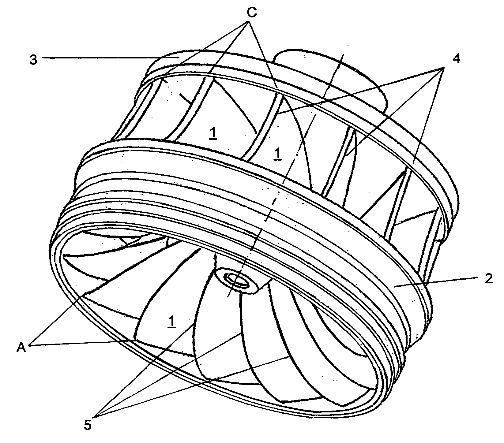
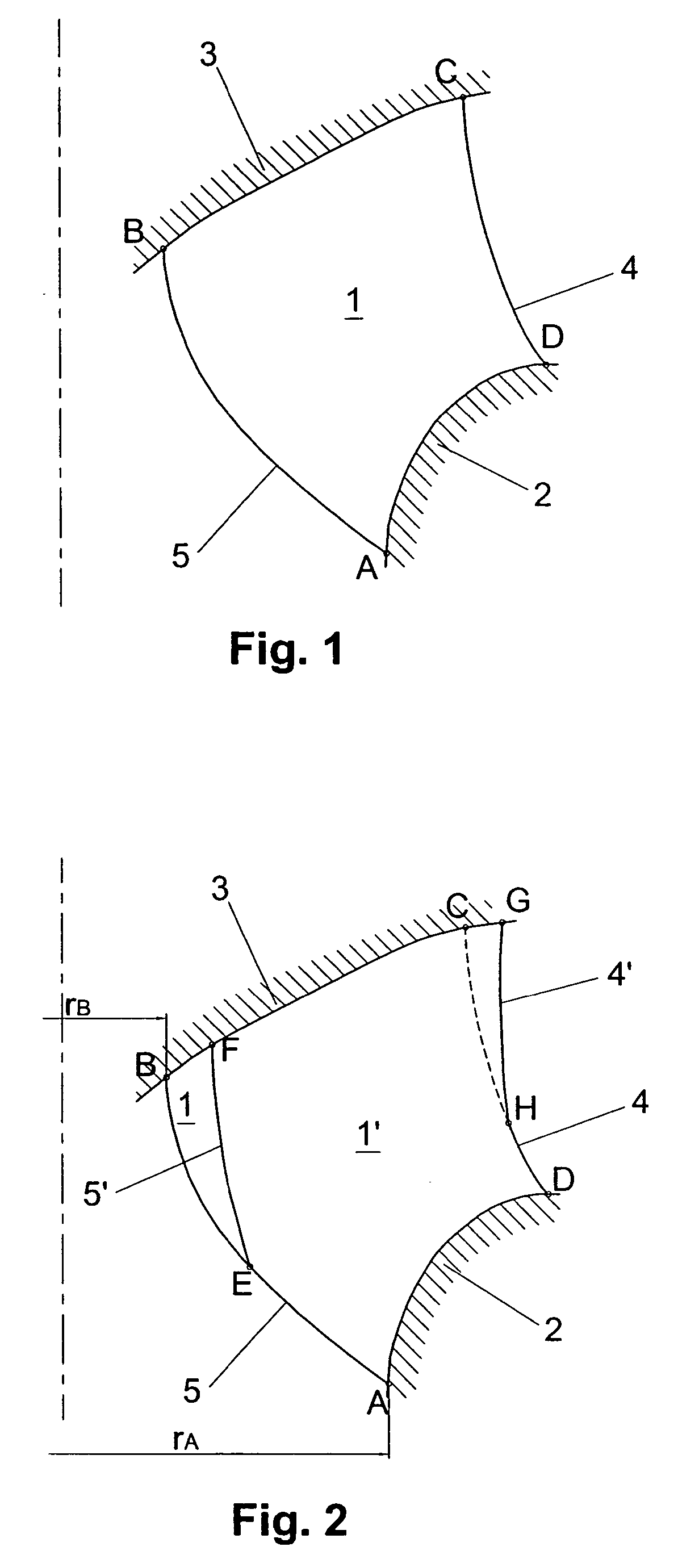
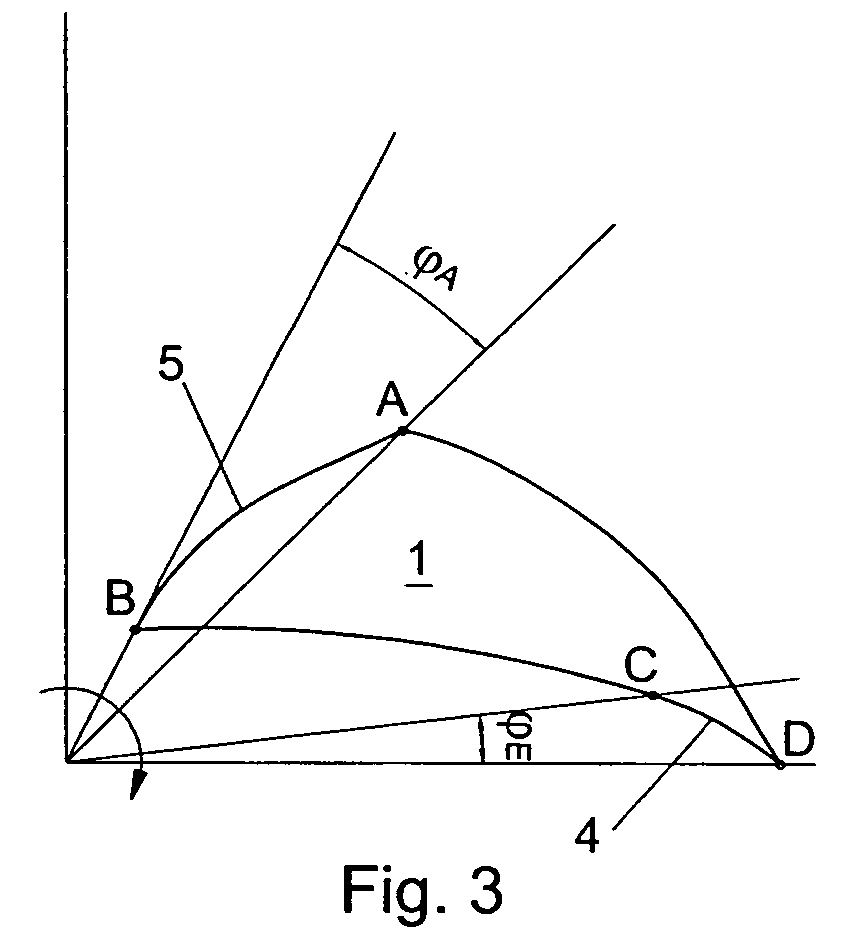
[0022] A conventional rotor blade 1 of a hydraulic machine, e.g. a turbine, pump-turbine or radial pump, is shown in FIG. 1. As shown in FIG. 4, the blade 1 is arranged between an inner 3 cover disk and an outer 2 cover disk. The blade has an inlet edge 4 and an outlet 5 edge which intersect the inner 3 and the outer 2 cover disk at the four contact points A, B, C and D.

[0023] Adjacent rotor blades 1 form a flow duct, through which an operating medium, for example water, can flow. For a turbine, a flow would occur from the inlet edge 4, for example from a sufficiently known spiral casing and distributor, not illustrated here, to the outlet edge 5 and, further on, to a sufficiently known suction pipe, likewise not illustrated here, which issues into tail water. For a pump or pump-turbine in pumping mode, the flow direction would be reversed correspondingly, that is, here, from the outlet edge 5 to the inlet edge 4. By means of the flow of operating medium through the rotor, the hydr...


PUM


Abstract

Rotor blades of a hydraulic machine rotor are shaped such that the inlet edge and outlet edge of two adjacent rotor blades have varying profiles in different sections.

Description

CROSS-REFERENCE TO RELATED APPLICATION [0001] The present application is a continuation-in-part of PCT / EP2003 / 009990, filed 9 Sep. 2003, which claims priority of Austrian Application No. A 1447 / 2002, filed 26 Sep. 2002. The PCT International Application was published in the German language.BACKGROUND OF THE INVENTION [0002] The present invention relates to a rotor of a hydraulic machine, preferably a Francis turbine, Francis pump-turbine or radial or diagonal pump, with a number of rotor blades which are arranged between an inner and an outer cover disk, and the rotor blades having an inlet edge and an outlet edge. [0003] A rotor of a hydraulic machine, for example, a Francis turbine, is shown in FIG. 4 hereof. It has a plurality of rotor blades 1, each having an inlet edge 4 and an outlet edge 5. The blades 1 are arranged between an inner cover disk 3 and an outer cover disk 2. Two blades 1 forming a flow duct for an operating medium, for example water, and the operating medium flo...

Claims


Application Information

Patent Timeline
Patent Type & Authority Applications(United States)
IPC IPC(8): D04H1/00E02D19/18E04B1/64E04G23/02F01D1/02F03B3/02F03B3/12
CPCD04H1/4374D04H13/00Y02E10/223F03B3/125F05B2240/301F03B3/02Y02E10/20
Inventor KECK, HELMUT
Owner VA TECH HYDRO
Why Eureka
Try Eureka