

System and methods for optical stimulation of neural tissues
a neural tissue and optical stimulation technology, applied in the field of neural tissue stimulation, can solve the problems of difficult simultaneous excitation and recording of adjacent nerve fibers, limit data analysis,
- Summary
- Abstract
- Description
- Claims
- Application Information
AI Technical Summary
Benefits of technology
Problems solved by technology
Method used
Image

Examples
example 1
Nerve Preparation
[0060] Spraque-Dawley rats (300-350 g) and Leopard frogs (2-3 in.) were utilized for in vivo sciatic nerve preparations. The rats were anesthetized through intraperitoneal injection using a 50% urethane solution and maintained sedated for the duration of each experiment, while frogs were pithed so as to euthanize the animal while maintaining vital body functions and nerve conduction during dissection and stimulation. The skin overlying the rat sciatic nerve was shaved and disinfected, and dissected to expose the main trunk of the sciatic nerve to the level of the knee where the nerve begins to branch. Nerves were stimulated 1 mm distal to the first branch point on the main sciatic nerve trunk from which a muscle response was elicited in the hamstring. The main branch was stimulated, proximal to the branch point, only for compound nerve action potential (CNAP) recordings in order to create space for the action potential to propagate and allow recording electrodes di...
example 2
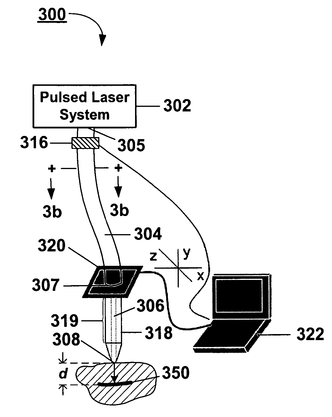
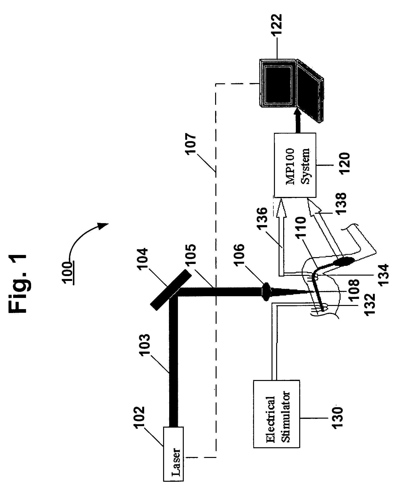
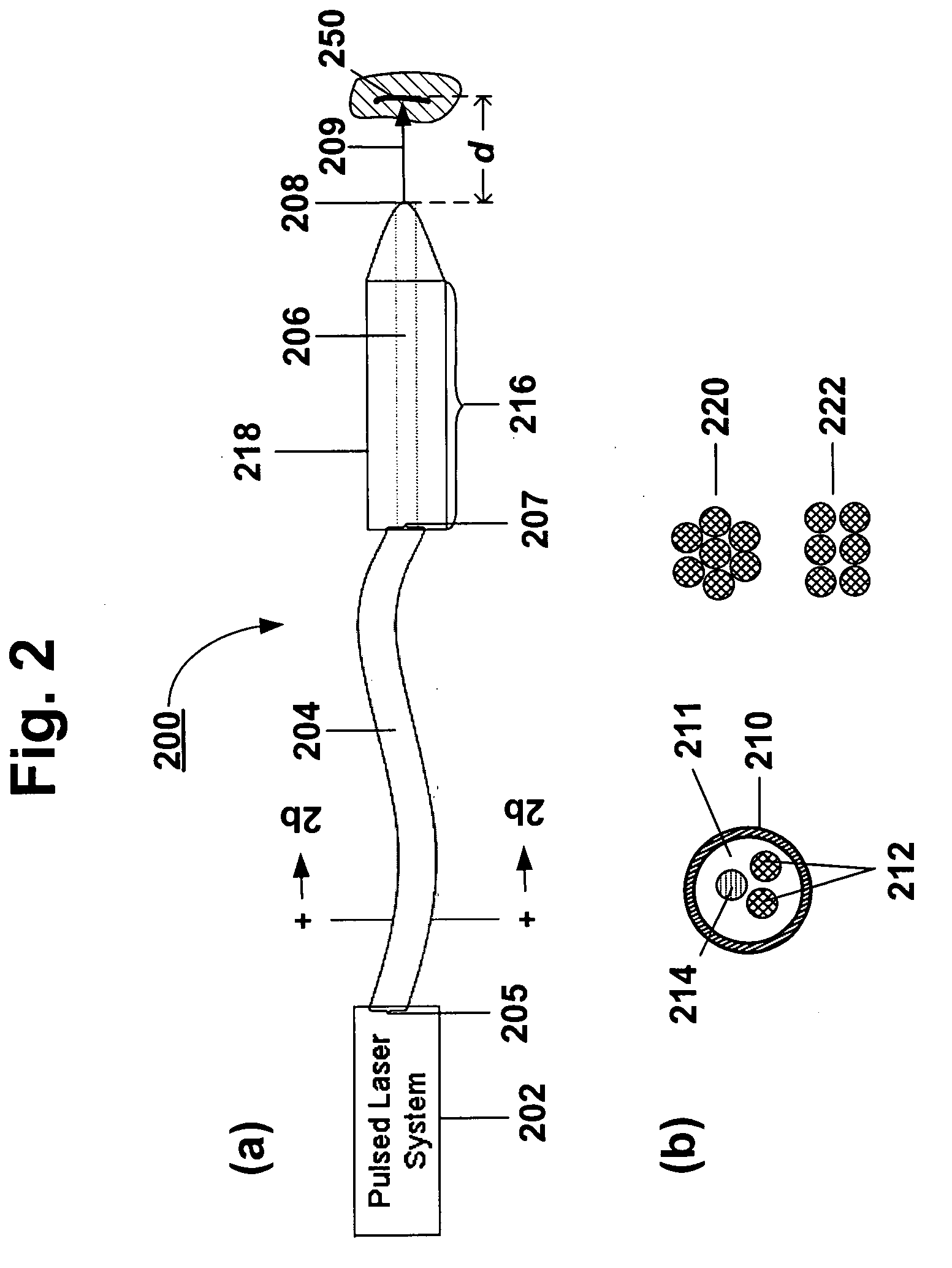
[0061] When using the tunable FEL source, the laser beam was directed using a series of infrared optics and mirrors under vacuum to the experimental setup. The FEL operates in the 2-10 μm region, with a unique pulse structure consisting of a train of 1 μs micro-pulses within a 5 μs macro-pulse. The laser was operated at 2 Hz and a helium-neon laser beam at 632.8 nm was co-aligned to the IR-FEL beam and used as an aiming laser. The beam was then focused using a focusing lens (bi-convex lens, f=300 mm) into a 500 μm hollow waveguide positioned slightly above the nerve sample. The small angle of divergence from the waveguide (6°) resulted in a spot size of 600 μm at the nerve. Laser pulse energy was varied by rotating a linear polarizer in the beam line. Optical stimulation was performed using laser pulses with radiant exposures from 0.3 J / cm2 to just above 1 J / cm2. Energies were measured using an energy meter (Molectron Inc).
[0062] A commercial Ho:YAG laser (Schwart...
example 3
Electrophysiological Recording
[0063] Electrical stimulation and recording were performed using an MP100 system (Biopac Systems, Santa Barbara, Calif.). At the beginning of every stimulation experiment, the sciatic nerve response to electrical stimulation was recorded using voltage pulses of 0.3-0.6V at pulse duration of 5 μs. The nerve response was recorded using silver chloride wire electrodes placed on the nerve 15 mm from the stimulation site for CNAP recording and needle electrodes pierced into the hamstring muscle 45 mm from the stimulation site for CMAP recording. The system is controlled using proprietary software (Acqknowledge®), through a communication card and displayed on the computer screen. During optical stimulus, data acquisition was triggered using a TTL voltage pulse synchronized with the output of the laser. Data recording was initiated 1-2 ms prior to the stimulus to observe baseline electrical activity. The CNAPs and CMAPs evoked from optical and electrical stim...
PUM
 Abstract
Description
Claims
Application Information