Electromagnetic brake for a multiple-ratio power transmission in a vehicle powertrain

a technology of power transmission and electric friction brake, which is applied in the direction of brake system, transmission, transportation and packaging, etc., can solve the problems of not readily becoming magnetized, ferrous particles in the operating environment of the transmission can be attracted to the rotary portion of the transmission, damage the transmission bearing, seal and other transmission components, etc., and achieve the effect of reducing the cross-sectional area

Inactive Publication Date: 2005-10-06
EATON INTELLIGENT POWER LIMITED
View PDF22 Cites 66 Cited by
  • Summary
  • Abstract
  • Description
  • Claims
  • Application Information

AI Technical Summary

Benefits of technology

[0017] The coil windings of the electromagnetic actuator for the input shaft brake is at a greater radius than the radius of the electromagnetic actuator disclosed in the co-pending application. The flux flow path thus is removed from close proximity to the input shaft. Further, the armature comprises a flexible plate with a restricted flux flow path therethrough. The plate may consist of a single annular ring or an annular ring with multiple sections, preferably four in number. Straps connect the ring to a center hub.

Problems solved by technology

The transmission housing, which typically is formed of cast aluminum or cast iron with a low carbon content, does not readily become magnetized because those materials are relatively poor conductors for magnetic flux fields.
Because of partial or residual magnetizati

Method used


Image

  • Electromagnetic brake for a multiple-ratio power transmission in a vehicle powertrain
  • Electromagnetic brake for a multiple-ratio power transmission in a vehicle powertrain
  • Electromagnetic brake for a multiple-ratio power transmission in a vehicle powertrain

Examples


Embodiment Construction

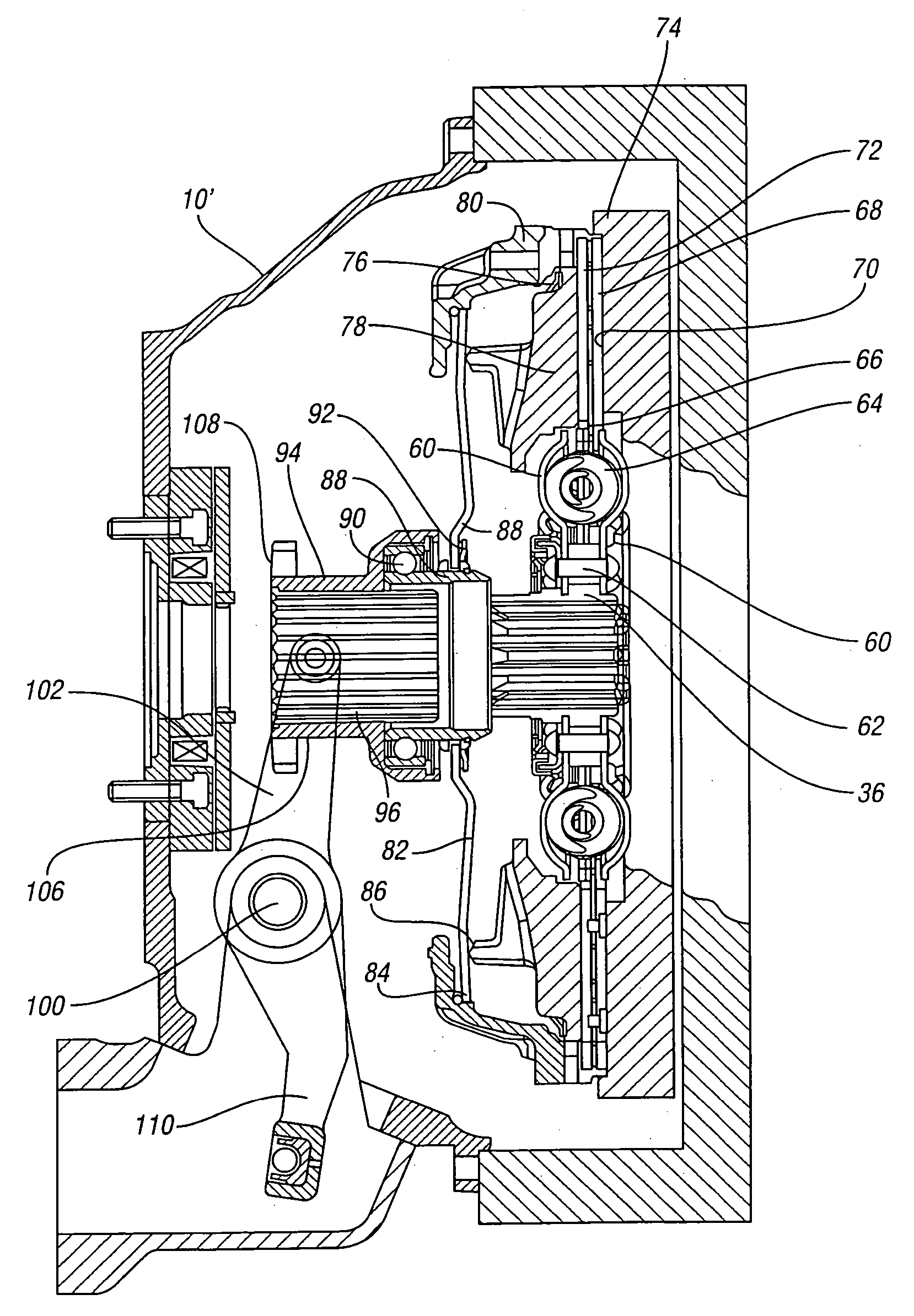
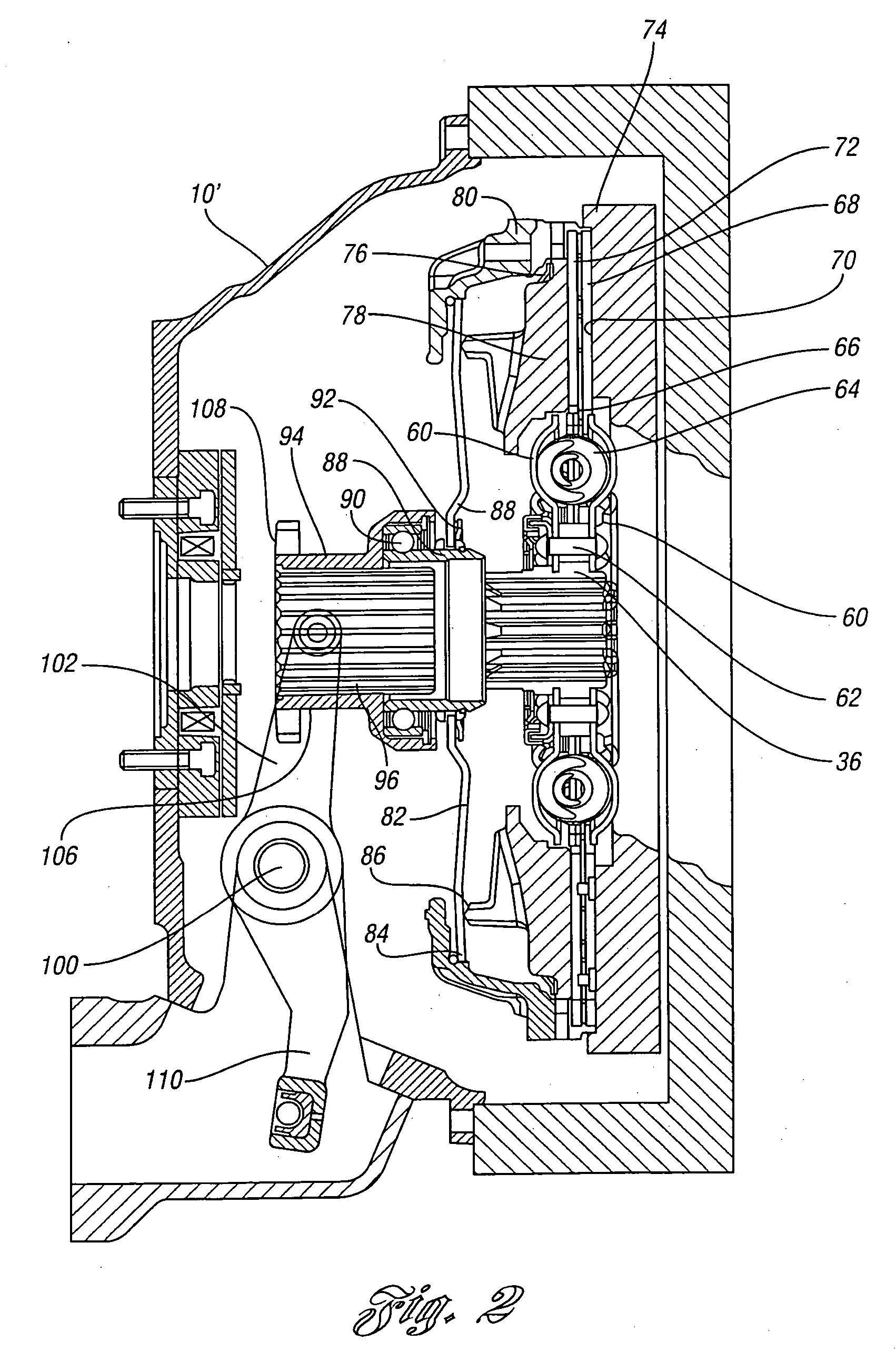
[0015] The invention comprises an electromagnetic brake for a transmission input shaft wherein the electromagnetic elements of the input shaft brake are isolated from bearing and seal areas of the transmission mechanism and from the input shaft itself. This is accomplished by providing large air gaps between the magnetic flux conductors and adjacent ferrous material. The flux conductors include the coil housing and the armature.

[0016] At those locations where the flux conductors must come into physical contact with components of the transmission, such as the mounting structure and the fasteners for securing the brake to the transmission housing, the mating components may be formed of non-magnetic materials, such as aluminum or stainless steel.

[0017] The coil windings of the electromagnetic actuator for the input shaft brake is at a greater radius than the radius of the electromagnetic actuator disclosed in the co-pending application. The flux flow path thus is removed from close p...


PUM


Abstract

An electromagnetic brake, including an electromagnetic brake actuator coil surrounding a power input shaft for a multiple-ratio transmission in a vehicle powertrain, is disclosed. An electromagnetic flux flow path for the actuator coil is electromagnetically isolated from the power input shaft and other elements of the powertrain thereby avoiding residual magnetization.

Description

CROSS-REFERENCE TO RELATED APPLICATIONS [0001] This application is a continuation-in-part of U.S. application Ser. No. 10 / 760,665, filed Jan. 20, 2004, entitled “Clutch Brake.”BACKGROUND OF THE INVENTION [0002] 1. Field of the Invention [0003] An electromagnetic friction brake for a heavy-duty power transmission for controlling deceleration of a torque input shaft for the transmission during transmission ratio changes. [0004] 2. Background Art [0005] A powertrain for a heavy-duty vehicle, such as a truck or a tractor trailer, typically has an engine that is connected driveably to a power input shaft for a multiple-ratio geared transmission by means of a so-called master clutch under the control of the vehicle driver. Driver operated shift rails and shift forks can be used to establish and disestablish torque flow paths through selected gear elements of the multiple-ratio transmission. Ratio changes can be accomplished manually by shifting synchronizer clutch sleeves into and out of ...

Claims


Application Information

Patent Timeline
IPC IPC(8): B60T1/06F16D65/14F16D67/02F16D67/06F16H3/12F16H61/04
CPCF16D67/02F16D67/06F16H2003/123F16D2123/00F16D2121/20
Inventor HORNBROOK, MICHAEL J.SCHENKEL, JOHN A.
Owner EATON INTELLIGENT POWER LIMITED
Why Eureka
Try Eureka