Photoionization detectors, ionization chambers for use in photoionization detectors, and methods of use of photoionization detectors

a technology of ionization chamber and detector, which is applied in the field of photoionization detector, can solve the problems of increasing the contamination of the window surface, slow decrease of the effective lamp output intensity with the operating time, and relatively difficult and expensive manufacture of the ionization chamber, and achieves the effect of less sensitive to ambient relative humidity

Active Publication Date: 2005-10-06
MSA TECH
View PDF11 Cites 3 Cited by
  • Summary
  • Abstract
  • Description
  • Claims
  • Application Information

AI Technical Summary

Benefits of technology

The present invention provides a photoionization detector with a housing and a removable photoionization chamber that can be easily replaced. The detector includes a first housing member and a second housing member that are mechanically connected to an insulating connector. The photoionization chamber includes a cathodic electrode and an anodic electrode. The detector also includes a VUV lamp to transmit VUV energy to the photoionization chamber. The invention also provides a photoionization chamber with a layer of nonconductive material on the electrodes to detect positively charged reaction products. The detector can be used in various applications such as environmental monitoring, industrial process control, and medical diagnostics.

Problems solved by technology

As a PID lamp is operated with its window exposed to trace hydrocarbon and organo-silicone compounds in a sample of ambient air, the window surface tends to become increasingly contaminated by a surface film which is formed from the photoionization products of these air-borne compounds.
This causes the effective lamp output intensity to decrease slowly with operating time.
For example, U.S. Pat. Nos. 5,773,833 and 6,225,633 disclose multilayer ionization chambers for a PID which are fabricated from multiple layers of machined PTFE and stainless steel, making the ionization chambers relatively difficult and expensive to manufacture.
Furthermore, with extended operating time the electrodes within the ionization chamber become contaminated by the process described above, resulting in leakage currents and inaccurate measurements.
It is quite difficult and relatively expensive to repair or restore an ionization chamber by opening it and removing this contamination.
However, these self-cleaning schemes also present disadvantages, which are discussed below.
Indeed, product specifications for a miniature LiF-window PID gas-discharge lamp which is available from RAE Systems, Inc., of Sunnyvale, Calif., indicate that the lamp is limited to an operating life of less than several hundred hours.
However, for a lamp with a LiF window this method exacerbates degradation of the LiF material due to color-center formation by the VUV radiation, and the repeated self-cleaning cycles will use up a significant fraction of its limited available operating life.

Method used


Image

  • Photoionization detectors, ionization chambers for use in photoionization detectors, and methods of use of photoionization detectors
  • Photoionization detectors, ionization chambers for use in photoionization detectors, and methods of use of photoionization detectors
  • Photoionization detectors, ionization chambers for use in photoionization detectors, and methods of use of photoionization detectors

Examples


Embodiment Construction

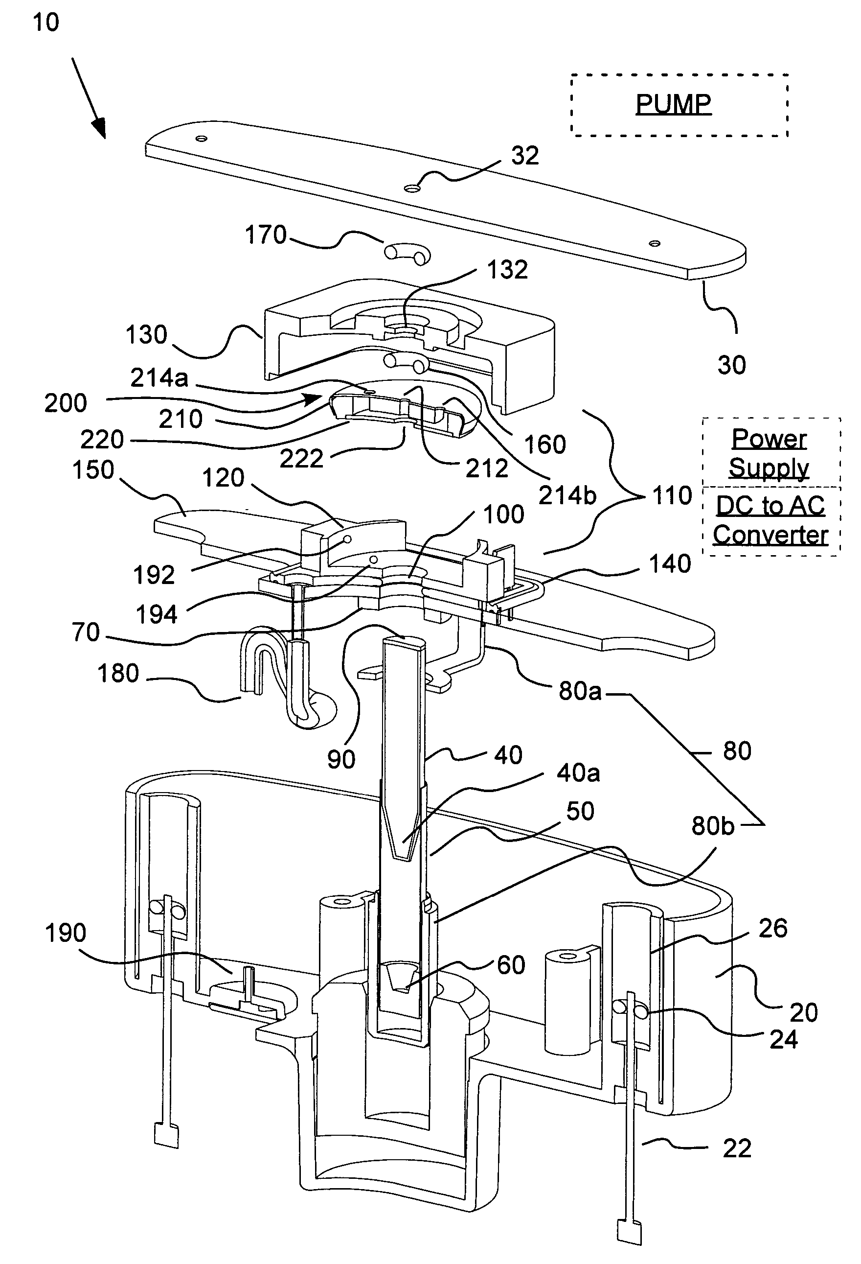
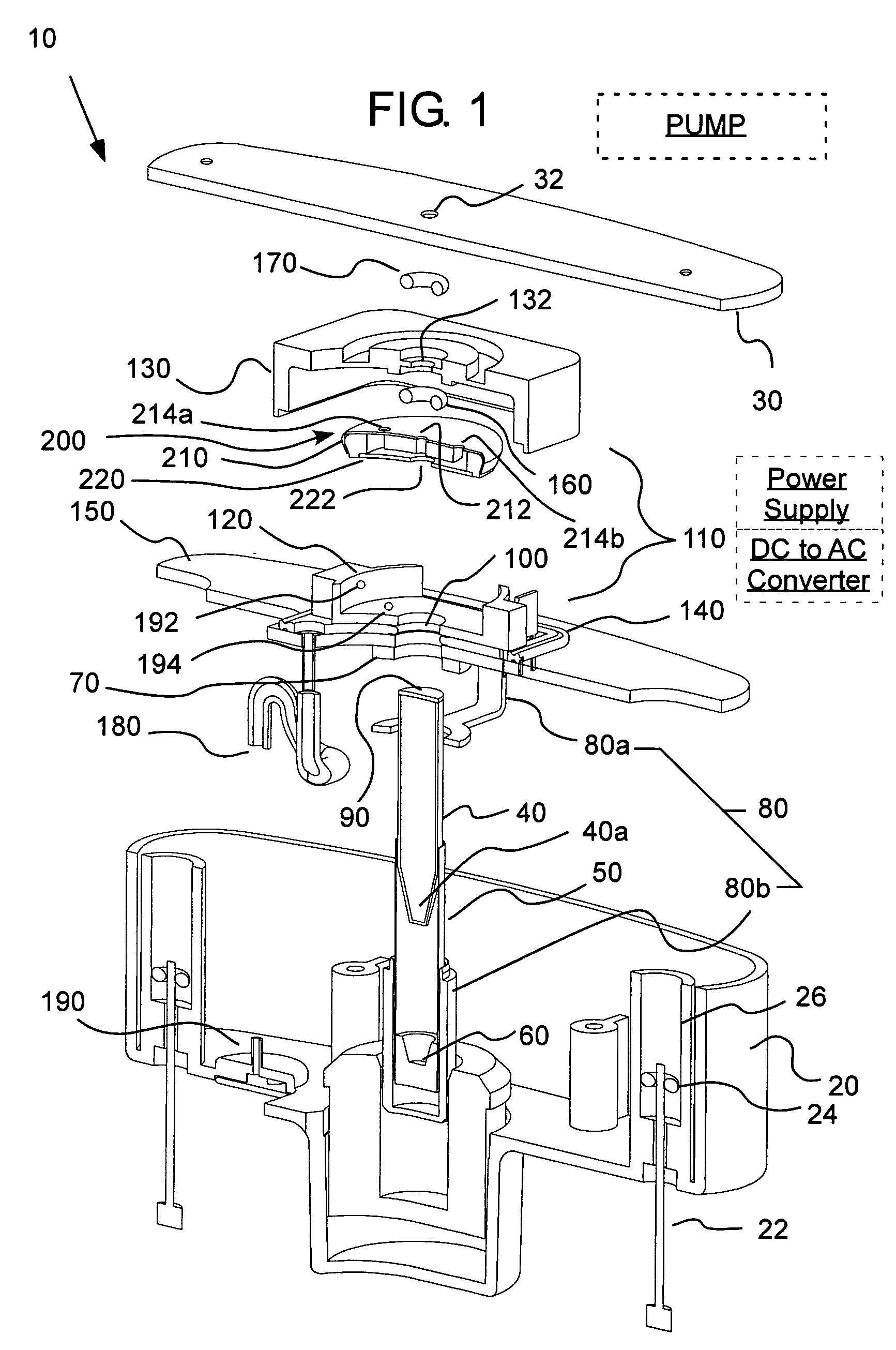
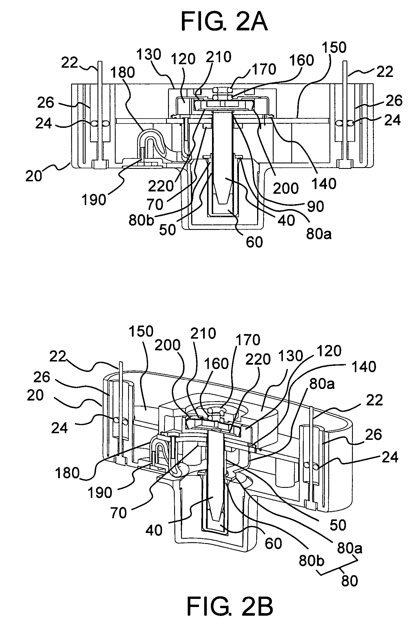
[0046]FIGS. 1 through 2B illustrate an embodiment of a PID 10 of the present invention, which can, in one embodiment include a detector housing 20 and a cooperating top enclosure or cap 30. Cap 30 can, for example, be maintained in connection with housing 20 via connectors such a screws 22. In the embodiment of FIGS. 1 through 2B, guides 24 (for example, annular members) guide screws 22 through a generally cylindrical screw well 26 to connect to cap 30.

[0047] As shown in FIG. 3A, housing 20 can also be connected to another housing 520 of an instrument 500, which can, for example, include one or more other gas sensors. Such other sensors can, for example, be electrochemical gas sensors. An embodiment of an ionization chamber 200a for use in a multi-sensor instrument is shown, for example, in more detail in FIGS. 5A-5D. As shown in FIG. 3B, the components of PID 10 can alternatively be incorporated within the housing 620 of a multi-sensor instrument assembly 600. In either case, some...


PUM

PropertyMeasurementUnit
thicknessaaaaaaaaaa
conductiveaaaaaaaaaa
shapeaaaaaaaaaa

Abstract

A photoionization detector includes a housing, electrical contacts within the housing and an easily removable and replaceable photoionization chamber within the housing. The photoionization chamber includes a cathodic electrode and an anodic electrode which may be coated with a thin layer of material. The photoionization chamber and the associated cathodic electrode and anodic electrode are removable from within the housing as a unit. The photoionization chamber makes electrical connection with the contacts when seated within the housing regardless of the orientation of the photoionization chamber about an axis.

Description

CROSS-REFERENCE TO RELATED APPLICATION [0001] This application claims the benefit of U.S. Provisional Patent Application No. 60 / 557,921 filed Mar. 31, 2004, the disclosure of which is incorporated herein by reference.BACKGROUND OF THE INVENTION [0002] The present invention relates generally to photoionization detectors, to ionization chambers for use in photoionization detectors, and to methods of use of photoionization detectors. [0003] Several photoionization detectors are described, for example, in U.S. Pat. Nos. 4,013,913; 4,398,152; 5,561,344; 6,225,633 and 6,646,444; and in German Patent DE 19535216 C1. In a typical photoionization detector (PID), a miniature gas-discharge lamp is used to produce high-energy vacuum ultraviolet (VUV) photons. In one approach, a large high-frequency voltage is applied between electrodes which are adjacent to the lamp bulb in order to induce an ionization, excitation and photoemission process in the gas which is sealed within the lamp bulb. Some ...

Claims


Application Information

Patent Timeline
Patent Type & Authority Applications(United States)
IPC IPC(8): G01N27/66
CPCG01N27/66
Inventor HAVERSTICK, JON K.BRUCE, DANIEL E.SCHULMAN, MICHAEL B.ZANELLA, MARK F. SR.CAHALL, JAMES A.MILLER, JAMES B.
Owner MSA TECH
Why Eureka
Try Eureka