Optical pickup apparatus

a technology of optical pickup and optical disc, which is applied in the field of optical pickup apparatus, can solve the problems of insufficient capacity to ensure appropriate recording/reproduction of information using high-density optical disc, inconvenient product downsizing and cost reduction, etc., and achieves the effect of low production cost and simplified construction

Inactive Publication Date: 2005-10-06
KONICA MINOLTA OPTO
View PDF15 Cites 26 Cited by
  • Summary
  • Abstract
  • Description
  • Claims
  • Application Information

AI Technical Summary

Benefits of technology

[0009] In view of the prior art described above, it is an object of the present invention to provide an optical pickup apparatus carrying an objective optical system. This objective optical system has a phase structure and provides adequate recording and / or reproduction of information using three types of discs having different recording densities including a high-density optical disc based on a blue-violet laser light source, DVD and CD. This optical pickup apparatus is further characterized by simplified construction and low production cost.

Problems solved by technology

Incidentally, the value of the optical disc player / recorder as a commercial product cannot be made sufficient merely by the capability of providing appropriate recording / reproduction of information using the high-density optical disc of this type.
In view of the fact that a DVD and CD (Compact Disc) carrying a great variety of information are currently placed on the market, the capability of ensuring appropriate recording / reproduction of information using the high-density optical disc is not sufficient.
However, this method requires use of a plurality of optical systems, and is not suited for product downsizing and cost cutdown.
In the optical pickup apparatus, this makes it difficult to standardize the optical components other than the objective optical system or to use the light source module where multiple types of light sources are integrated.
For this reason, simplification of the configuration of the optical pickup apparatus or cost reduction cannot be achieved.
This has created a problem in prior art.
Another problem in the prior art is found in the increased comatic aberration at the time of lens tracking, due to a large magnification for recording / reproduction of information with the CD in particular.

Method used


Image

  • Optical pickup apparatus
  • Optical pickup apparatus
  • Optical pickup apparatus

Examples


embodiment 1

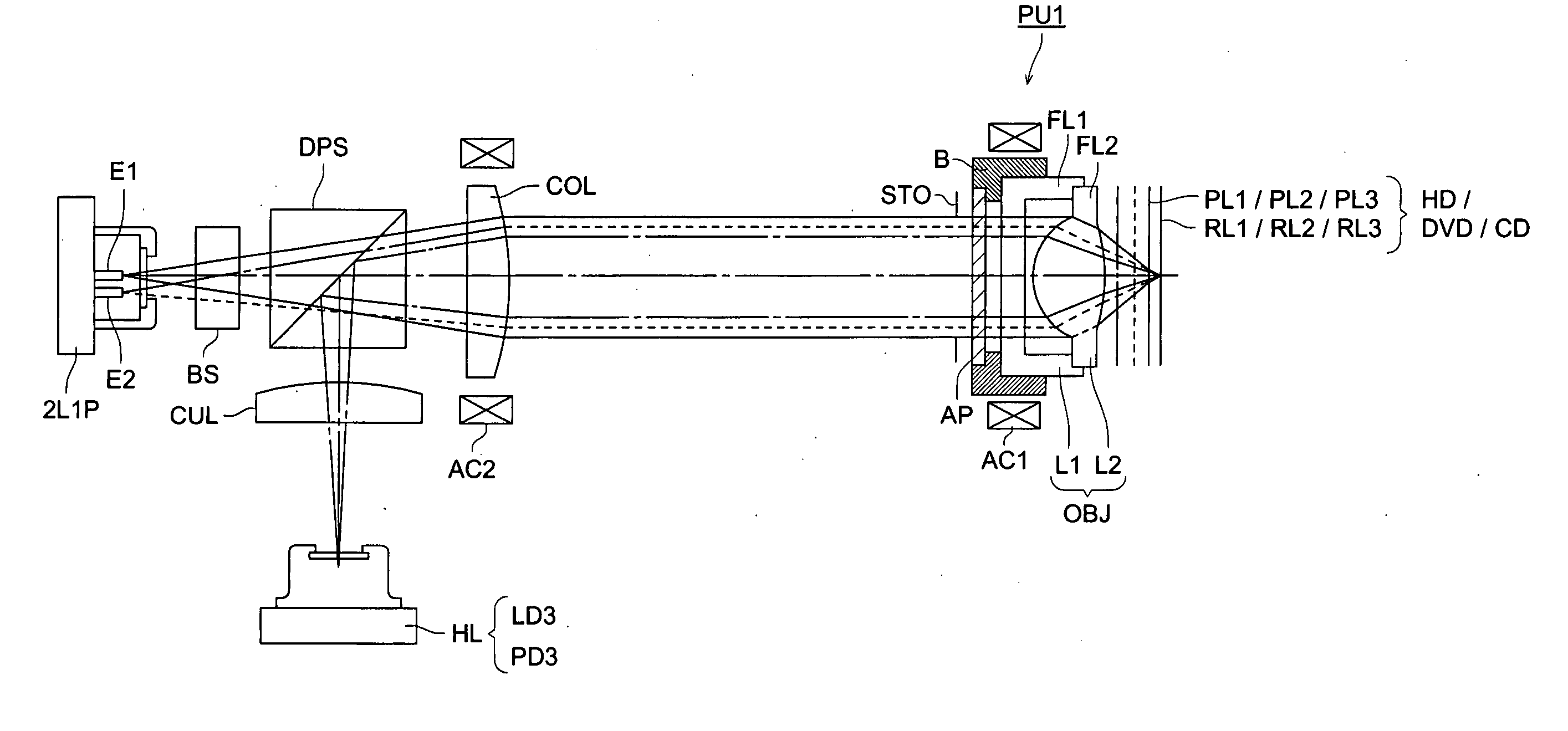
[0086]FIG. 5 is a schematic view of a configuration of first optical pickup apparatus PU1 capable of adequate recording / reproduction with a simple configuration, using any one of high-density optical disc HD (first optical disc), DVD (second optical disc) and CD (third optical disc). In terms of optical specifications, high-density optical disc HD is characterized by first wavelength λ1 of 408 nm, first protective layer PL1 having a thickness t1 of 0.1 mm and numerical aperture NA1 of 0.85. The DVD is characterized by the second wavelength λ2 of 658 nm, the second protective layer PL2 having a thickness t2 of 0.6 mm, and the numerical aperture NA2 of 0.60. The CD is characterized by the third wavelength λ3 of 785 nm, the third protective layer PL3 having a thickness t3 of 1.2 mm, and the numerical aperture NA3 of 0.45.

[0087] The relationship of the recording densities (ρ1, ρ2 and ρ3) among the first, second and third optical discs can be represented as ρ3<ρ2<ρ1. When information is...

embodiment 2

[0132]FIG. 7 is a schematic view of a simple configuration of second optical pickup apparatus PU2 that provides appropriate recording / reproduction of information using any of high-density optical disc HD (first optical disc), DVD (second optical disc) and CD (third optical disc). In terms of optical specifications, high-density optical disc HD is characterized by first wavelength λ1 of 408 nm, first protective layer PL1 having a thickness t1 of 0.1 mm and numerical aperture NA1 of 0.85. The DVD is characterized by the second wavelength λ2 of 658 nm, the second protective layer PL2 having a thickness t2 of 0.6 mm, and the numerical aperture NA2 of 0.60. The CD is characterized by the third wavelength λ3 of 785 nm, the third protective layer PL3 having a thickness t3 of 1.2 mm, and the numerical aperture NA3 of 0.45.

[0133] The relationship of the recording densities (ρ1, ρ2 and ρ3) among the first, second and third optical discs can be represented as ρ30. However, the combinations am...

embodiment 3

[0148]FIG. 8 is a schematic view of a configuration of third optical pickup apparatus PU3 that provides appropriate recording / reproduction of information using any of high-density optical disc HD (first optical disc), DVD (second optical disc) and CD (third optical disc). In terms of optical specifications, high-density optical disc HD is characterized by first wavelength λ1 of 408 nm, first protective layer PL1 having a thickness t1 of 0.1 mm and numerical aperture NA1 of 0.85. The DVD is characterized by second wavelength λ2 of 658 nm, the second protective layer PL2 having a thickness t2 of 0.6 mm, and the numerical aperture NA2 of 0.60. The CD is characterized by third wavelength λ3 of 785 nm, the third protective layer PL3 having a thickness t3 of 1.2 mm, and the numerical aperture NA3 of 0.45.

[0149] The relationship of the recording densities (ρ1, ρ2 and ρ3) among the first, second and third optical discs can be represented as ρ30. However, the combinations among the waveleng...


PUM

PropertyMeasurementUnit
first wavelength λ1aaaaaaaaaa
wavelengthaaaaaaaaaa
diameteraaaaaaaaaa

Abstract

An optical pickup apparatus comprises a first light source for emitting a first light flux having first wavelength λ1 (430 nm>λ1>380 nm), a second light source for emitting a second light flux having second wavelength λ2 (λ2>λ1), an objective optical system having phase structure thereon, and at least one moving optical element for guiding the light flux into the objective optical system, the moving optical element being moved in a direction parallel to an optical axis corresponding to the first light wavelength λ1 and the second light wavelength λ2, wherein the objective optical system has phase structure and satisfies M1=M2=0, where, M1 and M2 denote a first and second magnifications of the objective optical system for recording and/or reproducing the information on or from the first and second optical information media.

Description

[0001] This application claims priority from Japanese Patent Application No. 2004-109867 filed on Apr. 2, 2004, which is incorporated hereinto by reference. TECHNICAL FIELD [0002] The present invention relates to an optical pickup apparatus capable of recording and / or reproducing information using different types of optical information recording media in an interchangeable manner. BACKGROUND OF THE INVENTION [0003] In the field of an optical pickup apparatus in recent years, there has been an increasing tendency toward the use of short wavelength for the laser light source used as a light source for reproduction of the information recorded on an optical disc and for recording of information on the optical disc. For example, there have been efforts made for commercial use of a laser light source having a wavelength of 400 through 420 nm such as in a blue-violet semiconductor laser and blue-violet SHG laser for converting the wavelength of an infrared semiconductor laser using the sec...

Claims


Application Information

Patent Timeline
Patent Type & Authority Applications(United States)
IPC IPC(8): G11B7/00G11B7/135G11B7/125G11B7/1275G11B7/1353G11B7/1367G11B7/1378G11B7/1392
CPCG11B7/1275G11B7/1353G11B2007/0006G11B7/1378G11B7/13927G11B7/1367
Inventor HASHIMURA, JUNJIKIMURA, TOHRUMIMORI, MITSURU
Owner KONICA MINOLTA OPTO
Why Eureka
Try Eureka