Multiple access system and method for multibeam digital radio systems

Inactive Publication Date: 2005-10-06
MONSEN PETER
View PDF20 Cites 52 Cited by
  • Summary
  • Abstract
  • Description
  • Claims
  • Application Information

AI Technical Summary

Benefits of technology

[0017] With the foregoing background in mind, it is an object of the invention to provide a multiple acc

Problems solved by technology

However, in OMA radio systems, such cross-channel attenuation usually does not reduce interference enough to allow the reuse of the same orthogonal waveform or channel in adjacent beams.
Practical limitations on multibeam antennas typically cause the reuse factor in cellular OMA systems to vary between ⅓ and 1/12.
However, one drawback is that a QOMA radio system generally has a theoretical capacity that is less than that of an OMA radio system.
Al

Method used


Image

  • Multiple access system and method for multibeam digital radio systems
  • Multiple access system and method for multibeam digital radio systems
  • Multiple access system and method for multibeam digital radio systems

Examples


Example

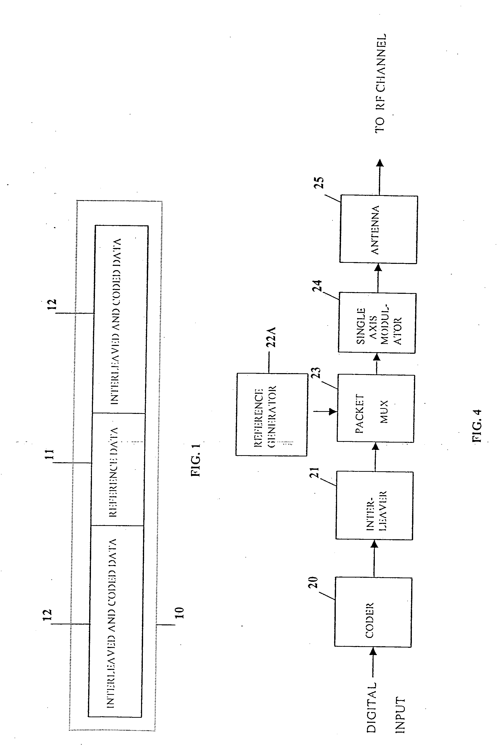
[0031]FIG. 1 shows the transmission format for a packet 10 of user message information to be sent over a reverse link or an uplink in a multiple access radio system between a fixed remote user terminal or a mobile user terminal and a central node, which may be located at either a fixed location on the Earth in a terrestrial radio system or as part of an orbiting satellite in a satellite radio system.

[0032] Data group 10 includes a user reference signal that is a block of reference data 11, which is inserted into the data group 10 at the user terminal. In particular, the reference data 11 includes a sequence of known data symbols (not shown) that may be inserted into the data group 10 either as a contiguous block as depicted in FIG. 1 or in some distributed manner. The sequence of data symbols and the manner in which they are inserted into the data group 10 are known at the central node for each user in the multiple access radio system whose message information is to be processed at...


PUM


Abstract

A multiple-access digital radio communication system and method with communication links between user terminal transmitters and a central node with a receiver system including a multibeam antenna. User terminal transmitters assigned to one beam coverage region use multiple access channels that are mutually orthogonal for transmitting digital message information that is included in a data group. Assignments are random and are changed for successive data groups. The same multiple access channels are reused in adjacent and other beam coverage regions each with an independent random assignment algorithm. Error-correction coding and interleaving are used in the user transmitter and an adaptive processor is used in the receiver. A reference sequence unique to either each user or each beam coverage region is multiplexed into user data groups for transmission. At the receiver the adaptive processor such as an equalizer or sequence estimator is used to combine multiple antenna beam signals to produce a combined signal associated with each user. The combining in the adaptive processor reduces interference from user terminal transmitters associated with different beam coverage regions but with the same multiple access channel. Deinterleaving and error-correction decoding of the combined signal are used to protect against channel assignments with larege mutual interference levels. The communication system can reuse each orthogonal multiple access channel in all of the other beams, i.e., a reuse factor of unity for each multiple access channel.

Description


Claims


Application Information

Patent Timeline
Owner MONSEN PETER
Why Eureka
Try Eureka