
Low reflectance optical coupling

a low reflectance, optical coupling technology, applied in the field of optical packages, can solve the problems of not being able to detect the characteristically higher attenuation loss of multimode fibers over single-mode fibers, and the unlikely optical coupling of reflected light back into the single-mode fiber, so as to improve the air gap optical coupling and reduce the effect of reflective loss

Inactive Publication Date: 2005-10-06
TE CONNECTIVITY CORP
View PDF1 Cites 11 Cited by
  • Summary
  • Abstract
  • Description
  • Claims
  • Application Information

AI Technical Summary

Benefits of technology

[0010] The present invention provides for an improved air gap optical coupling between a single mode fiber and another optical component. Specifically, the optical coupling of the present invention uses a section of multimode fiber at the interface of the single mode fiber and the air gap. One end of the multimode fiber is in physical contact with the single mode fiber. As mentioned above, this is a low reflectance optical coupling. The other end of the multimode fiber interfaces with the air gap. Although a beam emanating from the multimode fiber and into the air gap will face significant Fresnel reflection at the interface of the fiber and air, reflected light is unlikely to optically couple back into the single mode fiber. That is, since the diameter of a multimode fiber core is significantly larger than that of a single-mode fiber, light propagating in the multimode fiber is unlikely to couple with the single-mode fiber. Therefore, the multimode fiber stub acts essentially as a one-way check valve for light, allowing light to emanate from the single-mode fiber into the multimode fiber, but preventing reflective light from coupling back into the single-mode fiber. Preferably, the air / fiber interface of the multimode fiber is angled such that reflected light is projected into and absorbed by the fiber's cladding to further reduce reflective loss.
[0011] In addition to reducing reflectance, the optical coupling configuration of the present invention also offers a number of other advantages over the prior art. For example, the optical package can have relaxed tolerance. Specifically, the housing assembly can be produced using low cost machining techniques since alignment of the multimode fiber with a single mode fiber does not require a high degree precision. That is, the relatively large core diameter of the multimode fiber provides a large target for receiving optical signals from the single-mode fiber. Providing that the optical component which is coupled to the multimode fiber does not require the alignment precision of a single mode light (e.g., a photodiode), the reduction in precision of the optical beam from the single mode fiber to the multimode fiber will have no detrimental affect on the optical package. Furthermore, since the multimode fiber is so short (i.e., it is preferably only a stub), the characteristically higher attenuation losses of a multimode fiber over a single-mode fiber will not be noticed.
[0012] In addition to the relaxing the tolerances of the package, the optical coupling of the present invention also allows critical alignments to be made internal to the housing before mating with the single mode fiber. That is, rather than dealing with radial positioning an angled single mode fiber in the optical package, which requires keying the single mode fiber to the optical package, the present invention allows the angled face of multimode fiber to be positioned and fixed within the housing during assembly and prior to connection with the single mode fiber. This way, the radial orientation of the angled fiber end face is set in a controlled manufacturing environment and the single mode fiber can be introduced at a later time without regard to radial alignment. This reduces costs and simplifies coupling of the single mode fiber with the optical package.

Problems solved by technology

Although a beam emanating from the multimode fiber and into the air gap will face significant Fresnel reflection at the interface of the fiber and air, reflected light is unlikely to optically couple back into the single mode fiber.
Furthermore, since the multimode fiber is so short (i.e., it is preferably only a stub), the characteristically higher attenuation losses of a multimode fiber over a single-mode fiber will not be noticed.

Method used


Image

  • Low reflectance optical coupling
  • Low reflectance optical coupling
  • Low reflectance optical coupling

Examples


Embodiment Construction

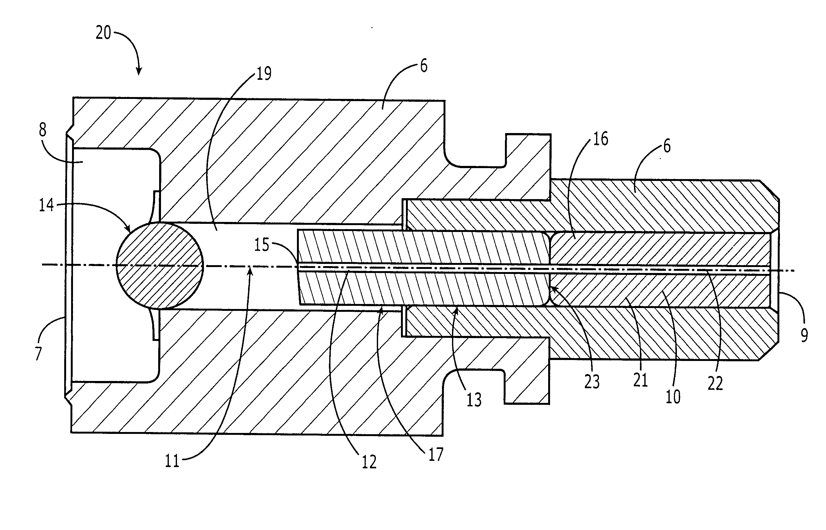
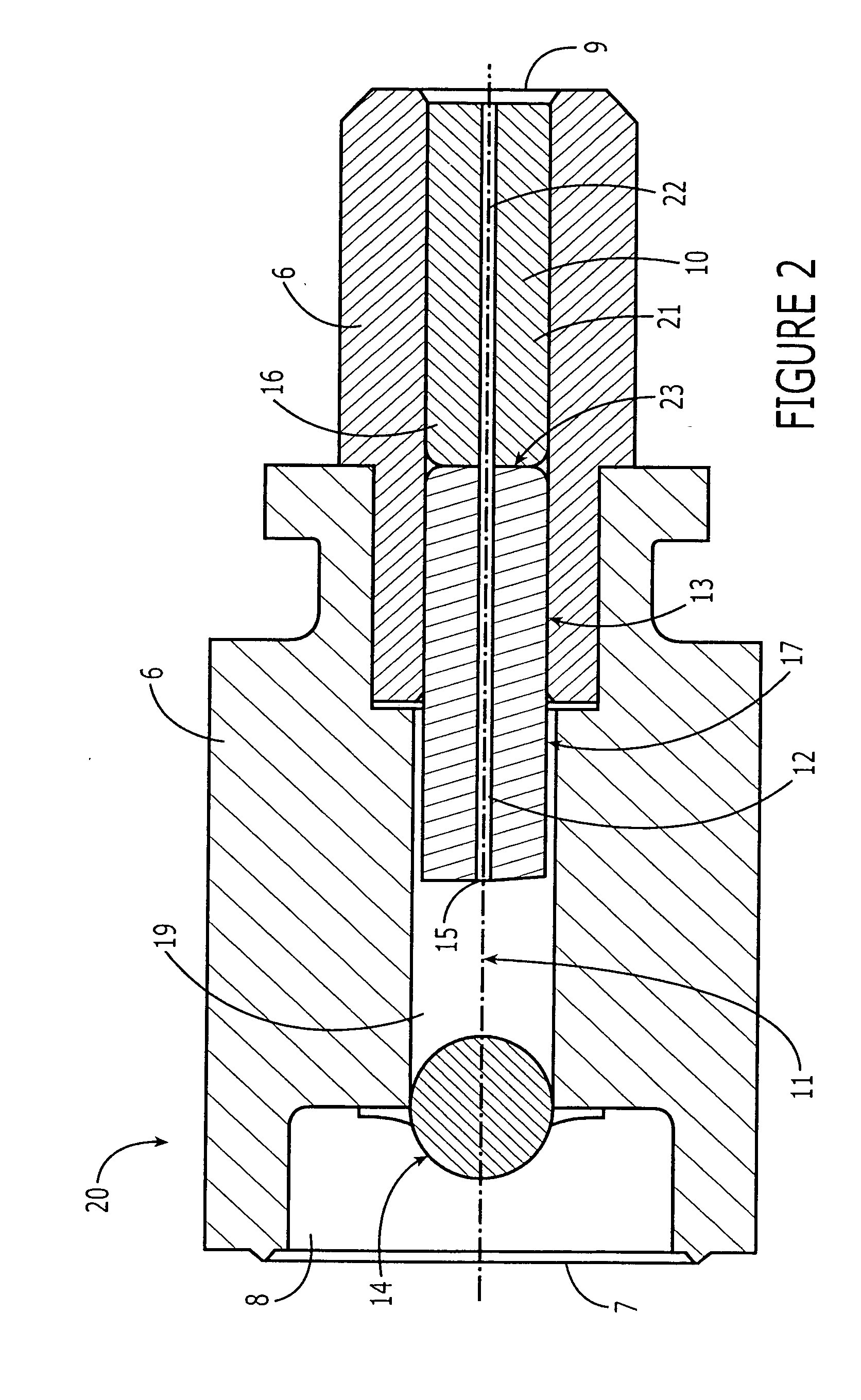
[0020] Referring to FIGS. 2-5, an optical coupling of the present invention is shown. For illustrative purposes, an optical connector interface (OCI) 20 will be considered herein specifically. It should be understood, however, that the present invention is not limited to an OCI, but can be practiced with any optical package involving a single mode fiber with a fiber / air interface.

[0021] The OCI 20 comprises a housing 6 having an optical axis 11, a first end 7 with a corresponding first cavity 8, and a second end 9 with a corresponding second cavity 10. The housing may be integrally molded or it may be an assembly of discrete components. The first cavity 8 of the housing is designed to receive an optical component, which, in this embodiment, is a ball lens 14, and that the second cavity 10 is designed to receive a single mode fiber 22, which, in this embodiment, is contained in a ferrule 21. The ferrule 21 holds the fiber 22 such that it is aligned along the housing's optical axis 1...


PUM


Abstract

An optical coupling comprising: (a) a housing having first and second ends and having an optical axis, the first end having a first cavity for receiving an optical component, the second end having a second cavity for receiving a single mode fiber along the optical axis; and (b) a section of a multimode fiber disposed within the housing and along the optical axis between the first and second cavities, the multimode fiber having a first fiber end and a second fiber end, the first fiber end interfacing with air, the second fiber end being polished to optically couple with the single mode fiber through physical contact.

Description

CROSS REFERENCE TO RELATED APPLICATIONS [0001] This application claims priority benefit to U.S. Provisional Application No. 60 / 515,369 filed on Oct. 29, 2003, which is incorporated herein by reference.FIELD OF INVENTION [0002] The invention relates generally to an optical package, and, more specifically, to an optical package comprising a cavity for receiving a single mode fiber. BACKGROUND [0003] Optical packages are ubiquitous in optical systems. As used herein, the term “optical package” refers to any assembly of discrete optical components which are optically coupled to each other. Examples of optical packages include TO cans for transmitting and receiving optical signals, optical benches for manipulating optical signals, and add / drops for multiplexing and demultiplexing optical signals. Of particular interest herein are optical packages in which a single mode fiber is optically connected to an optical component, such as another fiber or an optoelectric device (OED). [0004] Refe...

Claims


Application Information

Patent Timeline
IPC IPC(8): G02B6/36G02B6/38G02B6/42
CPCG02B6/3818G02B6/421G02B6/4207
Inventor THOMPSON, ROSS JOB
Owner TE CONNECTIVITY CORP
Learn More