Trailer-mounted crane apparatus

a technology of cranes and apparatuses, applied in the field of cranes, can solve the problems of affecting the lifting capacity and reach of the crane, the area adjacent to the sheet piling, and the local area can be soft, uneven, etc., and achieves the effects of reducing surface pressure, maximizing lifting capacity and reaching, and light weigh

Inactive Publication Date: 2005-10-06
BURKETT DARRYL S
View PDF40 Cites 19 Cited by
  • Summary
  • Abstract
  • Description
  • Claims
  • Application Information

AI Technical Summary

Benefits of technology

[0009] Using the inventive apparatus, a sheet piling wall can be installed adjacent to soft, loose or uneven ground without difficulty. A trailer-mounted crane apparatus can be configured of a sufficiently light weight to be usable upon delicate ground surfaces, such as are present on a golf course, without damaging the surfaces, such as might occur using a heavier truck-mounted crane or a back hoe. The preferred embodiment crane apparatus of the present invention is compact and usable in close quarters compared to the aforementioned larger truck-mounted cranes or back hoes. The preferred embodiment crane apparatus of the present invention includes wide tires for reducing the surface pressure under the trailer. This allows the trailer to be transported across, and staged on, delicate surfaces such as golf course greens.
[0010] The preferred embodiment crane apparatus of the present invention comprises a trailer-mounted crane apparatus having a component layout on the trailer that maximizes lifting capacity and reach. The layout includes the hydraulic crane having a vertical center post located centrally of the trailer and having its elongated hydraulic fluid cylinder mounted longitudinally; the crane hydraulic power unit mounted to the front and laterally of the crane center post; the control panel and the associated operator's seat mounted to the front of the crane hydraulic power unit; and the vibratory driver hydraulic power unit mounted in front of the crane. The trailer includes outriggers at the rear corners adjacent respectively to the oversized tires. The trailer includes a vibratory driver cradle for securely holding the vibratory driver on the trailer during road transportation of the trailer. The cradle is located on the trailer laterally of, and behind, the crane on a side opposite to the operator's seat.

Problems solved by technology

One difficulty in driving sheet piling is related to a type of terrain that may be located adjacent to the area that is to receive the sheet piling.
Where sheet piling is to be driven adjacent to a pond, for example, the local area can be soft, or uneven.
On a golf course, for example, the area adjacent to the sheet piling, or access ways to that area, may be delicate and can be damaged by heavy equipment.

Method used


Image

  • Trailer-mounted crane apparatus
  • Trailer-mounted crane apparatus
  • Trailer-mounted crane apparatus

Examples


Embodiment Construction

[0021] While this invention is susceptible of embodiment in many different forms, there are shown in the drawings and will be described herein in detail specific embodiments thereof with the understanding that the present disclosure is to be considered as an exemplification of the principles of the invention and is not intended to limit the invention to the specific embodiments illustrated.

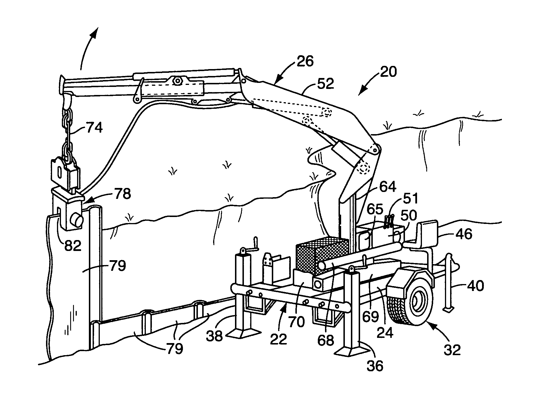
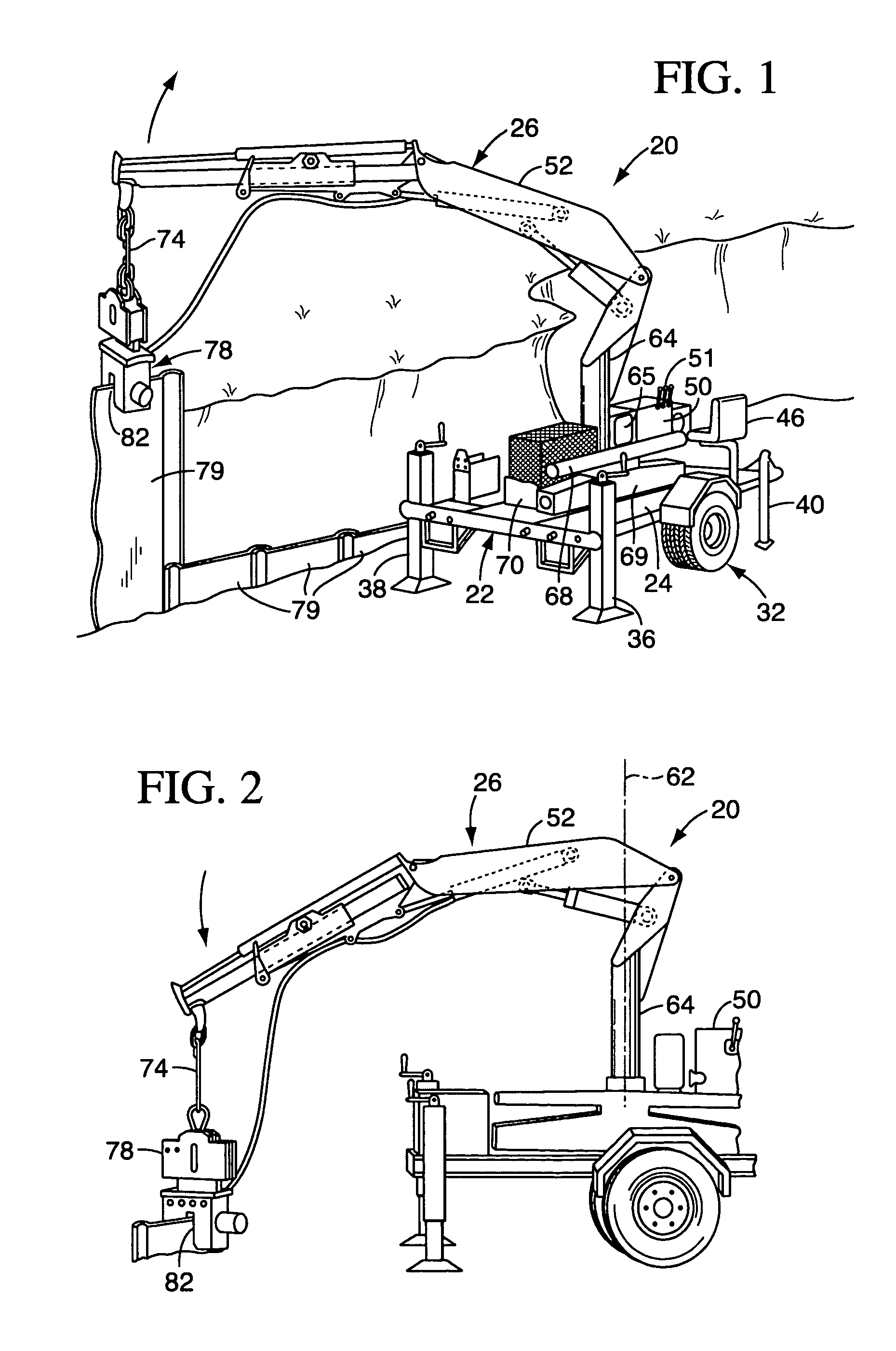
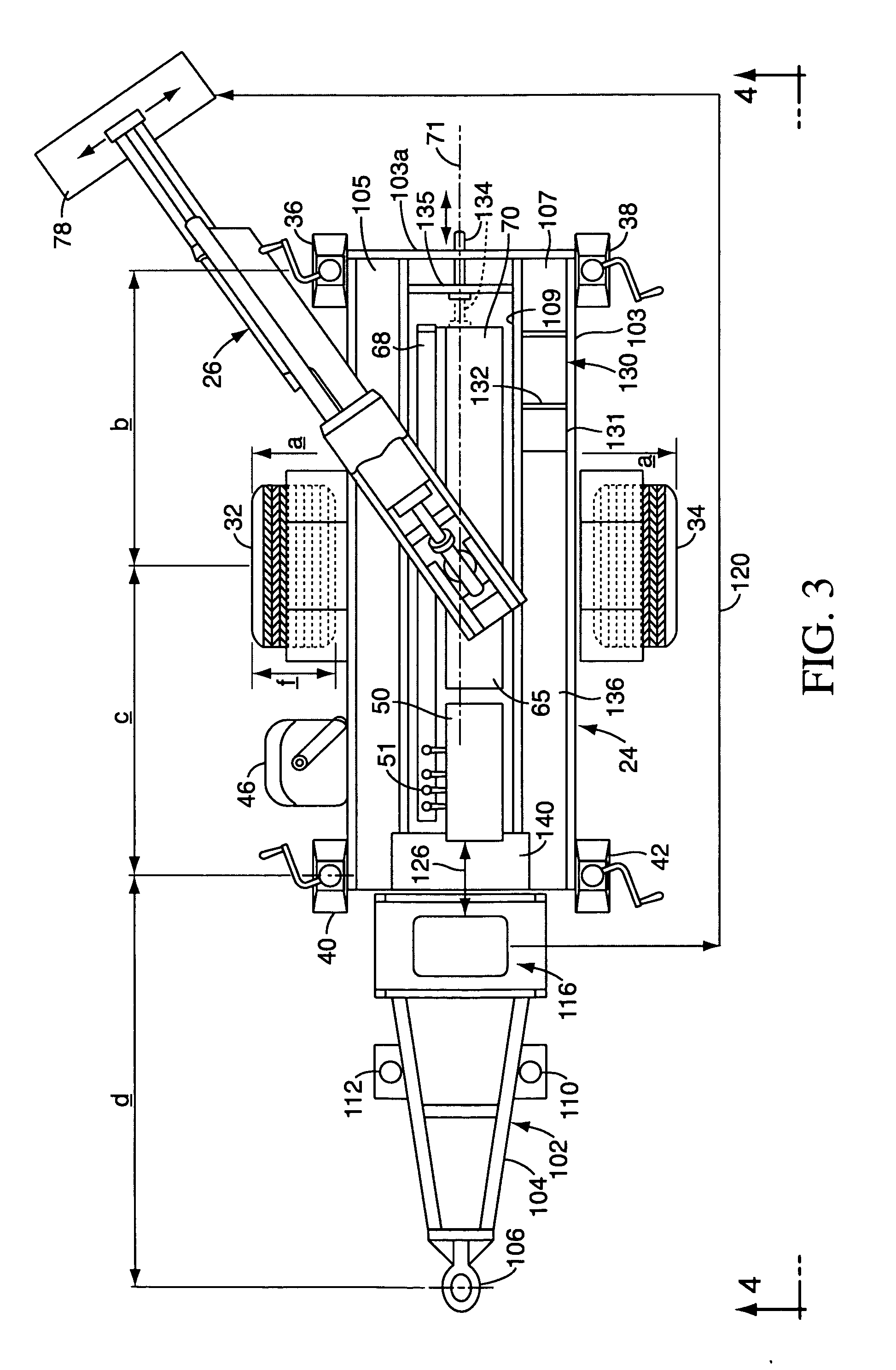
[0022]FIGS. 1 and 2 illustrates a trailer-mounted crane apparatus 20 in accordance with the present invention. The apparatus 20 includes a trailer 22 supporting a crane 26. The trailer 22 includes a platform 24 which surrounds the crane 26. The trailer 22 is supported on wheels 32, 34 (shown in FIG. 3). The trailer 22 can be further supported or stabilized by two or more outriggers 36, 38, 40, 42 (shown in FIG. 3) extending from the platform 24, which can be used to increase the overturning capacity of the crane, or to level the crane as needed. Attached to the platform 24 is an operator's seat 4...


PUM


Abstract

A trailer-mounted crane apparatus includes a trailer supported from a ground surface on at least two wheels. A hydraulically operated crane arm is mounted to the trailer and is extendable outwardly. A crane hydraulic power unit is mounted to the trailer and supplies pressurized hydraulic fluid to the crane arm. A vibrational sheet piling driver can be supported by the crane arm. A vibrational hydraulic power unit for supplying power to the driver is mounted on the trailer. A control panel for the crane hydraulic power unit and the vibrational driver hydraulic power unit, and an associated operator's seat, are also mounted on the trailer. The crane apparatus includes wide tires for reducing the surface pressure under the apparatus. This allows the apparatus to be transported across and used on delicate surfaces such as golf course greens and other groomed surfaces.

Description

TECHNICAL FIELD OF THE INVENTION [0001] The present invention relates to cranes, and particularly relates to a trailer-mounted crane which is useful in supporting a vibratory sheet piling driver. BACKGROUND OF THE INVENTION [0002] In landscaping architecture, there sometimes exists a need, particularly around water, for the protection of banks and other land formations from erosion, or a need to maintain a bank at an angle steeper than its natural soil angle of repose. This is sometimes accomplished by the use of sheet piling. [0003] In a typical sheet piling installation, individual, elongated steel sheets having channeled edges are driven into the soil, one after another, in interlocking fashion, to create a sheet piling wall. In this regard, a vibratory driver is sometimes used to drive the sheets into the ground. A typical vibratory driver includes a clamping jaw and a vibratory motor, both hydraulically driven by a separate, engine-driven hydraulic power unit. The driver is sus...

Claims


Application Information

Patent Timeline
Patent Type & Authority Applications(United States)
IPC IPC(8): E02D7/18B66C23/38B66C23/90B60P1/00
CPCB66C23/38E02D7/18
Inventor BURKETT, DARRYL SCOTT
Owner BURKETT DARRYL S
Why Eureka
Try Eureka