

Fuel cell stack
- Summary
- Abstract
- Description
- Claims
- Application Information
AI Technical Summary
Benefits of technology
Problems solved by technology
Method used
Image

Examples
example 1
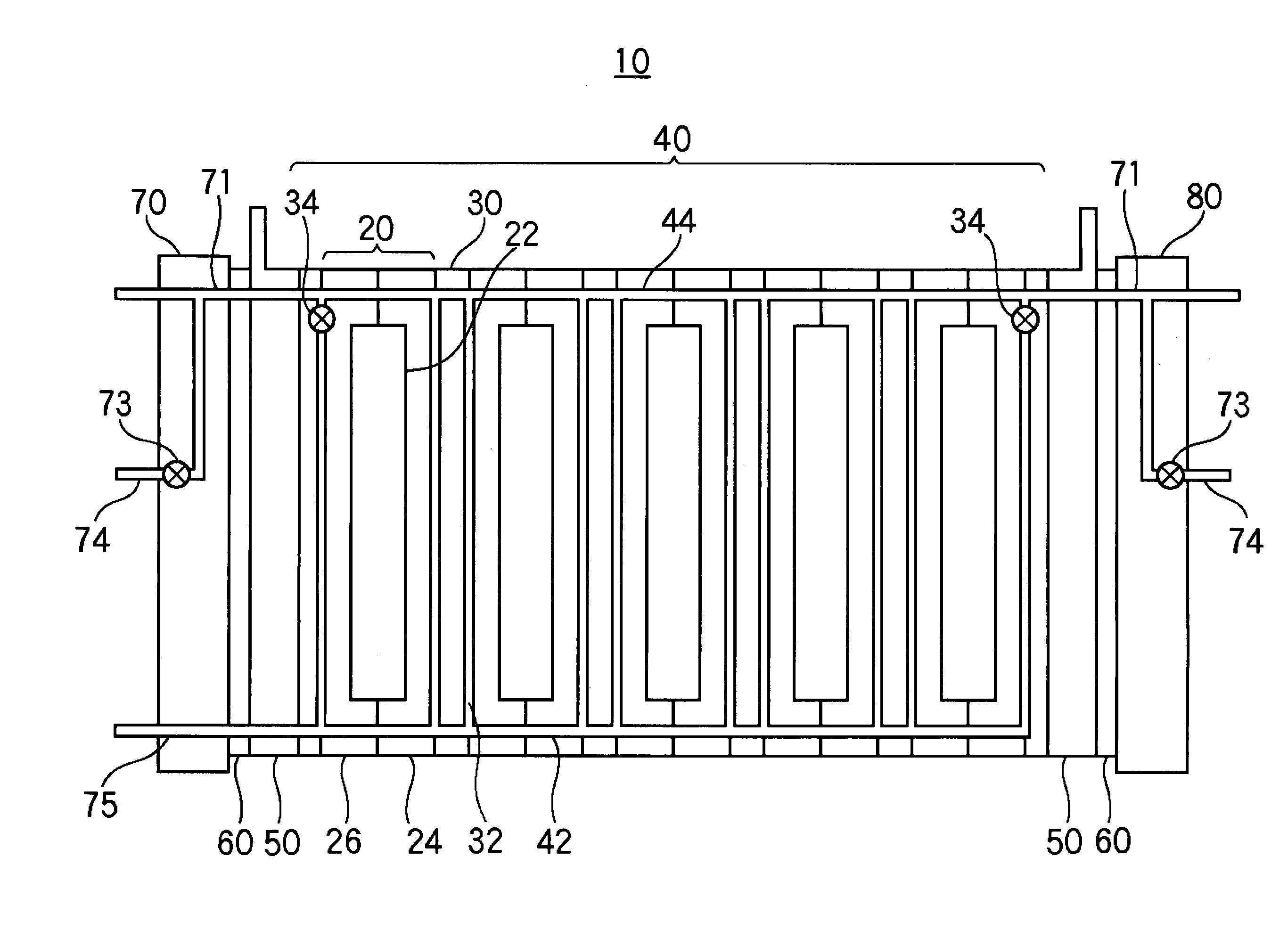
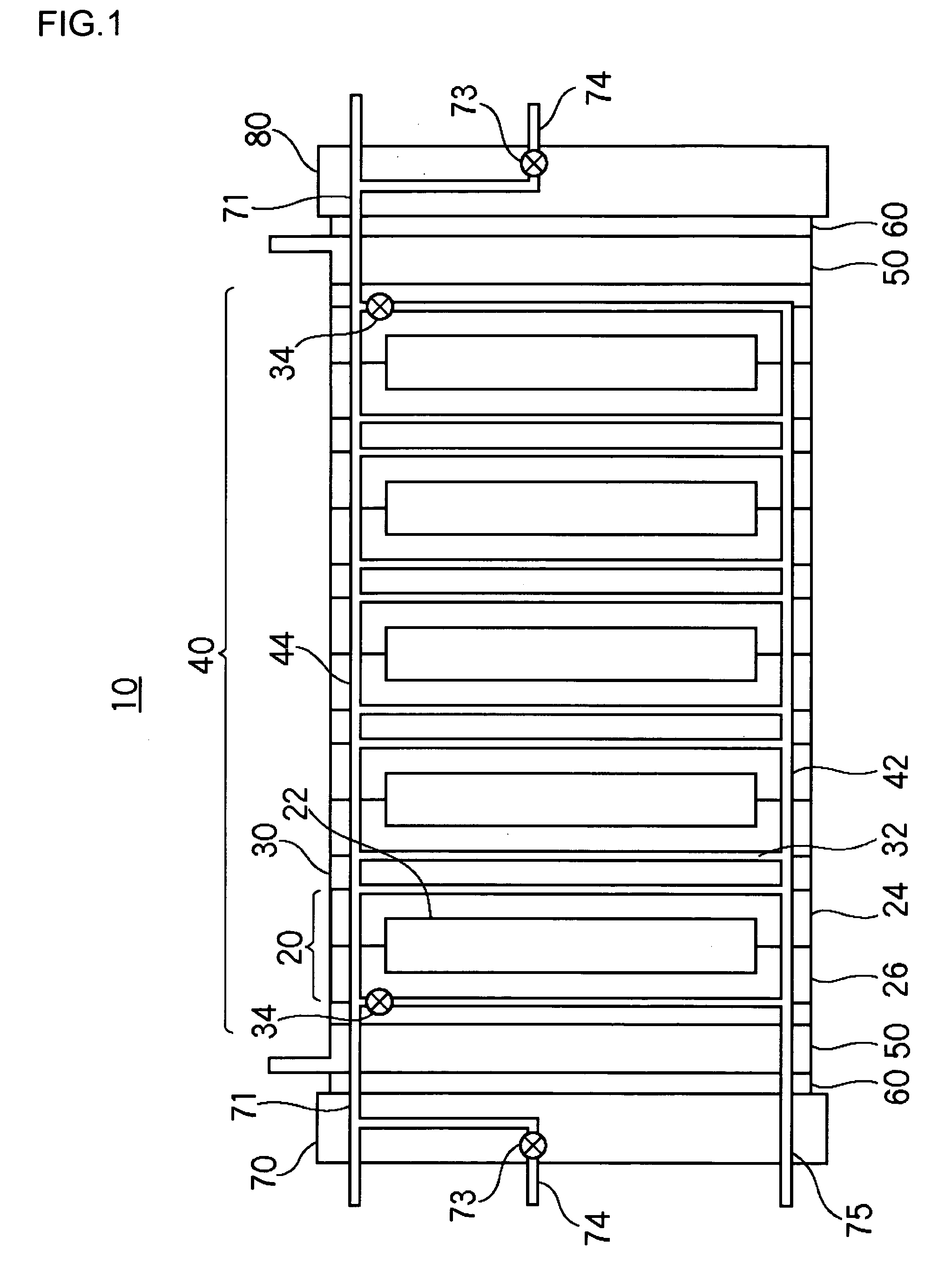
[0043]FIG. 1 is a schematic diagram illustrating the structure of a polymer electrolyte fuel cell stack according to example 1.
[0044] The polymer electrolyte fuel cell stack 10 comprises: a stack 40 in which a plurality of cells 20 and a plurality of cooling plates 30 sandwiched between the cells 20 are stacked; and end plates 70, 80 clamping the stack 40 at both ends of the stack 40 via current collector plates 50 and insulating plates 60.
[0045] The cell 20 is provided with an MEA 22, an anode plate 24 provided with a fuel passage facing an anode of the MEA 22, and a cathode plate 26 provided with an oxidant passage facing a cathode of the MEA 22. The cooling plate 30 is provided with a cooling water passage 32 in which cooling water used as a heat medium flows. In the vicinity of an outlet of the cooling water passage 32 of the cooling plates 30 located at respective ends of the stack is provided a flow rate control element 34 for controlling the flow rate of cooling water flowi...
example 2
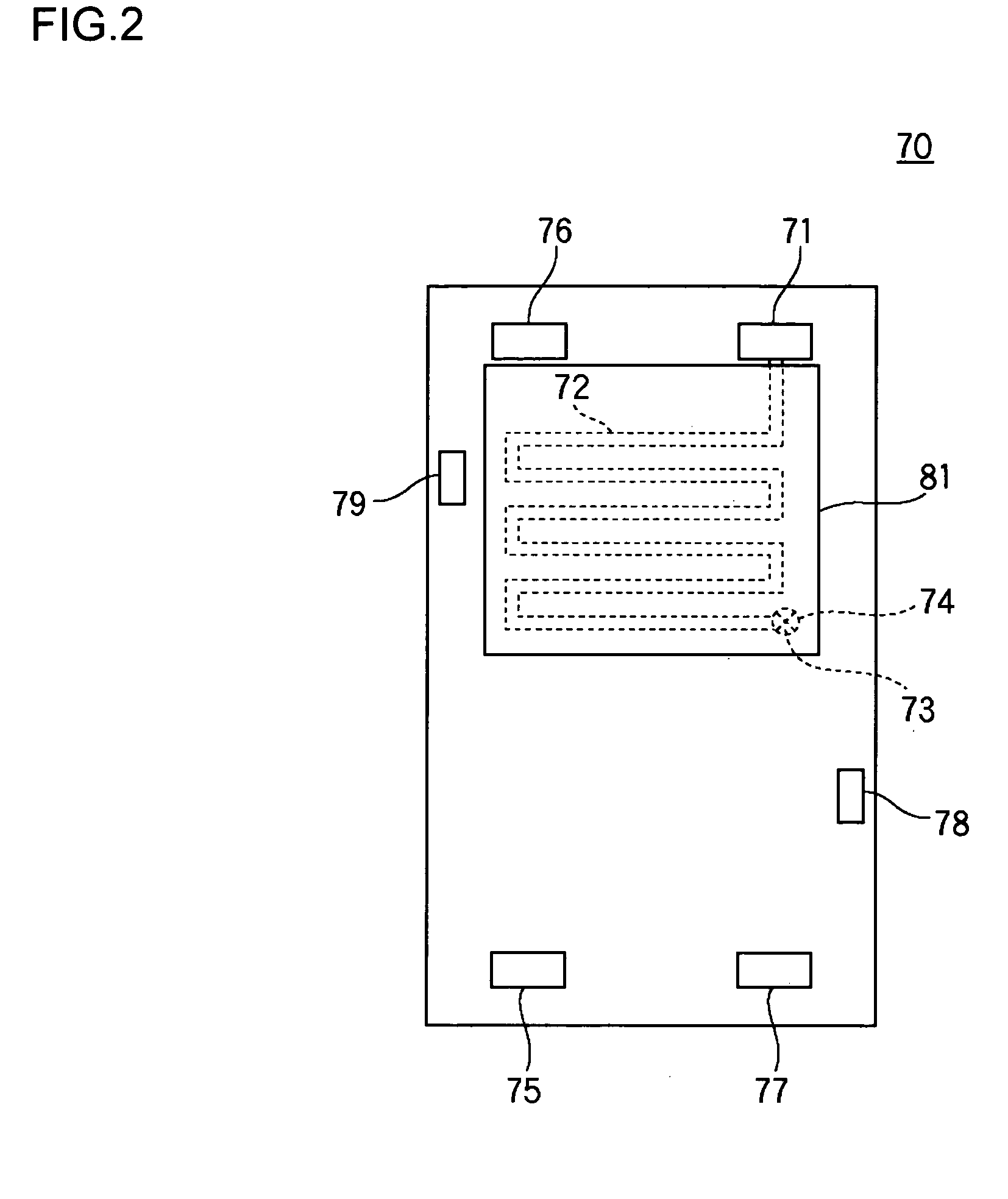
[0080]FIG. 8 is a schematic diagram illustrating the structure of an end plate of a polymer electrolyte fuel cell stack according to example 2. A stack end passage 72C of an end plate 70C according to example 2 shares common features with the passage of example 1 in that the passage is formed as a practically sigmoidal route at the upper area of the end plate 70C corresponding to the high-temperature area of the cells 20. A difference is that the stack end passage 72C according to example 2 has a larger sectional area toward the top of the end plate 70C. With this, the top part of the cells 20 at the stack ends are effectively heated by cooling water flowing the stack end passage 72C. Accordingly, it is ensured that the temperature of the cells 20 at the stack ends approximates that of the other cells 20.
example 3
[0081]FIG. 9 is a schematic diagram illustrating the structure of an end plate 70D of a polymer electrolyte fuel cell stack according to example 3. A stack end passage 72D of the end plate 70D according to example 3 shares common features with the passage of example 1 in that the passage is formed as a practically sigmoidal route at the upper area of the end plate 70D corresponding to the high-temperature area of the cells 20. A difference is that intervals between loop back segments of the route of the stack end passage 72D according to example 3 are smaller toward the upper part of the end plate 70D. With this, the upper part of the cells 20 at the stack ends are effectively heated by cooling water flowing in the stack end passage 72D so that it is ensured that the temperature distribution of the cells 20 at the stack ends approximates that of the other cells 20.
[0082] While the stack end passages in examples 1-3 are formed at the end plates 70 and 80, they may be formed in the c...
PUM
 Abstract
Description
Claims
Application Information