AGC circuit

Inactive Publication Date: 2005-10-06
SONY CORP
View PDF5 Cites 16 Cited by
  • Summary
  • Abstract
  • Description
  • Claims
  • Application Information

AI Technical Summary

Benefits of technology

[0012] The present invention provides an AGC circuit which comprises: a high frequency amplifier constituted of a variable gain amplifier; a first conversion circuit for converting a first AGC voltage into a first control current having predetermined characteristics; and a second co

Problems solved by technology

Under the reception conditions that a strong interference wave exists, there arises a problem of an S/N ratio lowered rather by interference signals.

Method used


Image

  • AGC circuit
  • AGC circuit
  • AGC circuit

Examples


Embodiment Construction

[0029] [1] Receiver

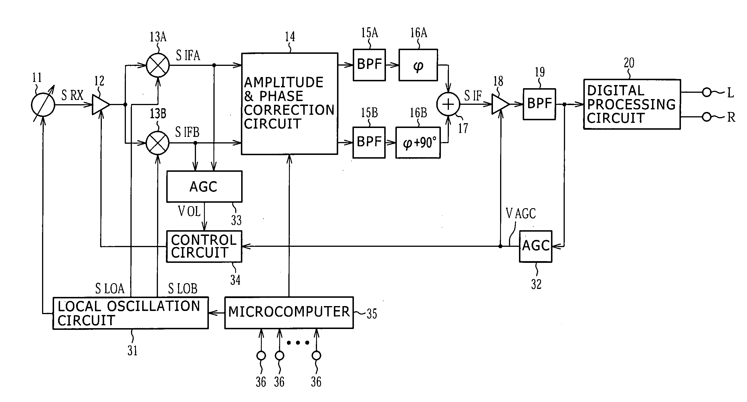
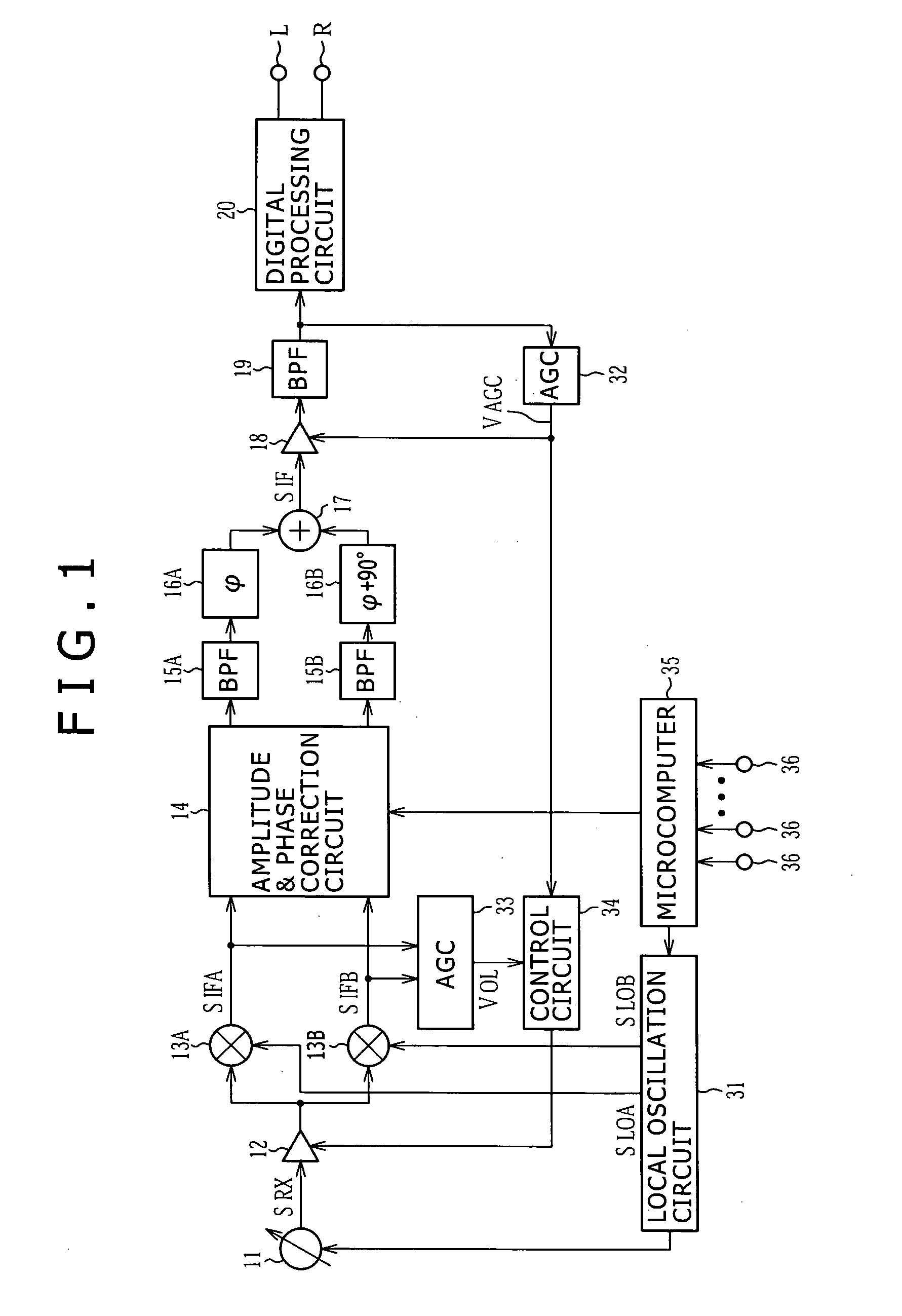
[0030]FIG. 1 shows an example of a receiver.

[0031] This receiver is of a so-called low IF (Intermediate Frequency) system in which an intermediate frequency is set much lower than a reception frequency by setting a local oscillation frequency near to the reception frequency. A reception signal is frequency-converted into a pair of orthogonal intermediate frequency signals, and the image characteristics are improved by phase processing.

[0032] Namely, a reception signal SRX having a target reception frequency is picked up from an antenna tuning circuit 11 of an electronic tuning type, and this reception signal SRX is supplied to a pair of mixer circuits 13A and 13B via a high frequency amplifier 12. A local oscillation circuit 31 is constituted of a PLL (Phase Locked Loop) circuit which generates two signals SLOA and SLOB having phases different by 90° and a frequency near to the frequency of the reception signal SRX (e.g., in the case of a receiver for a digital...


PUM


Abstract

An automatic gain control (AGC) circuit includes a number of attenuation circuits connected in series relative to a reception signal, a of variable gain amplifiers to which the reception signal and each output signal from the attenuation circuits are fed, respectively, a signal deriving circuit connected to output terminals of the variable gain amplifiers for deriving a level-controlled output signal, and a control current generating circuit for generating a control current having a predetermined characteristic out of first and second AGC voltages, wherein the control current outputted from the control current generating circuit is supplied to the variable gain amplifiers as a control signal for switching an operation thereof and for controlling a gain thereof, and a feedback control current corresponding to the control current is performed by the control current generating circuit.

Description

CROSS REFERENCES TO RELATED APPLICATIONS [0001] The present invention contains subject matter related to Japanese Patent Application JP 2004-111692 filed in the Japanese Patent Office on Apr. 6, 2004, the entire contents of which being incorporated herein by reference. BACKGROUND OF THE INVENTION [0002] 1. Field of the Invention [0003] The present invention relates to an AGC circuit of a radio receiver. [0004] 2. Description of Related Art [0005] An AGC (Automatic Gain Control) circuit at a high frequency stage of a radio receiver may be configured such as shown in FIG. 15. In FIG. 15, a reference numeral 1 represents an antenna tuning circuit, a reference numeral 2 represents a high frequency amplifier, and a reference numeral 3 represents a mixer circuit. The high frequency amplifier 2 is constituted of attenuator circuits 2A to 2C, variable gain amplifiers 2D to 2G, and an adder circuit 2H. [0006] Operation and non-operation of the amplifiers 2D to 2G are controlled by an AGC vol...

Claims


Application Information

Patent Timeline
IPC IPC(8): H04B1/06H03G3/30H03G1/00H03G7/00H03G3/20H04B1/16H04B17/02H04B7/00H04B1/10H04B17/40
CPCH03G1/0023H03G1/0088H03G3/3068H03G7/001H03G2201/103H03G2201/204H03G2201/305H03G2201/307H03G2201/506A63B5/20
Inventor OKANOBU, TAIWA
Owner SONY CORP
Why Eureka
Try Eureka