Linkage for a driver's cab

a driver's cab and linkage technology, applied in the field of driver's cabs, can solve the problems of driver's cab enough room to shift backward, high cost, and particularly serious situation, and achieve the effect of good deformation or crumpling characteristics, easy and inexpensive production

Inactive Publication Date: 2005-10-13
DAIMLER AG
View PDF13 Cites 12 Cited by
  • Summary
  • Abstract
  • Description
  • Claims
  • Application Information

AI Technical Summary

Benefits of technology

[0011] The catch plate may consist for instance of a stamped metal blank, making it easy and inexpensive to produce. It can be die-stamped or bent into the desired shape, obviating in its manufacture the need—unlike cast-metal components—for specially produced molds.
[0012] The catch plate may consist of a highly ductile material. The advantage of that is that the material is at once tough and very tractile. These properties are offered for instance by steel type S500MC (steel EN10149, material classification number 1.0984). In the event of an impact, these material properties make for good deformation or crumpling characteristics of the catch plate without exceeding the fa...

Problems solved by technology

The situation is particularly serious when the frame or chassis systems of the colliding vehicles extend at different levels, since in any such case the energy of the impact is not channeled directly into the frame system of either vehicle but instead strikes the components above and/...

Method used


Image

  • Linkage for a driver's cab
  • Linkage for a driver's cab
  • Linkage for a driver's cab

Examples


Embodiment Construction

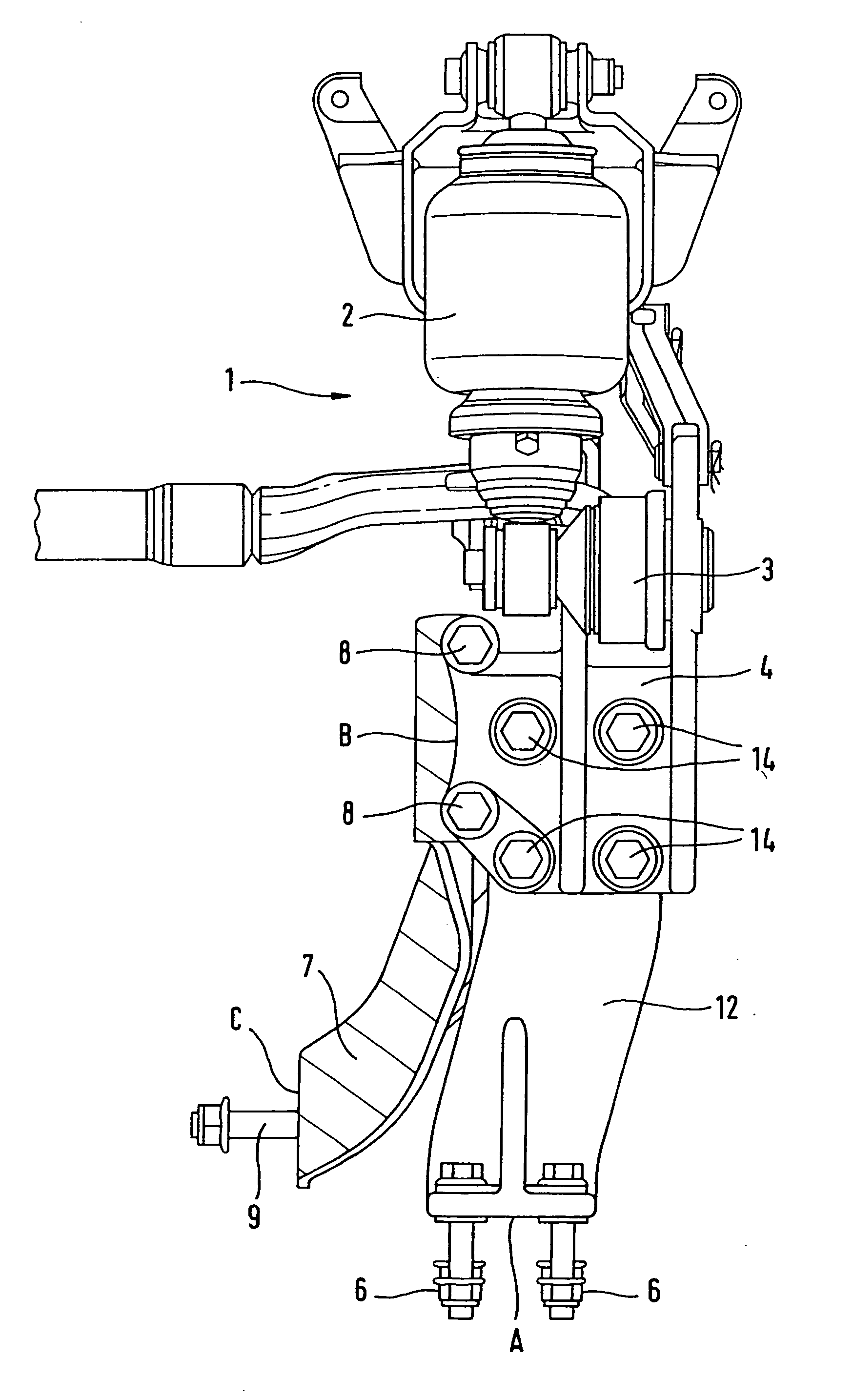
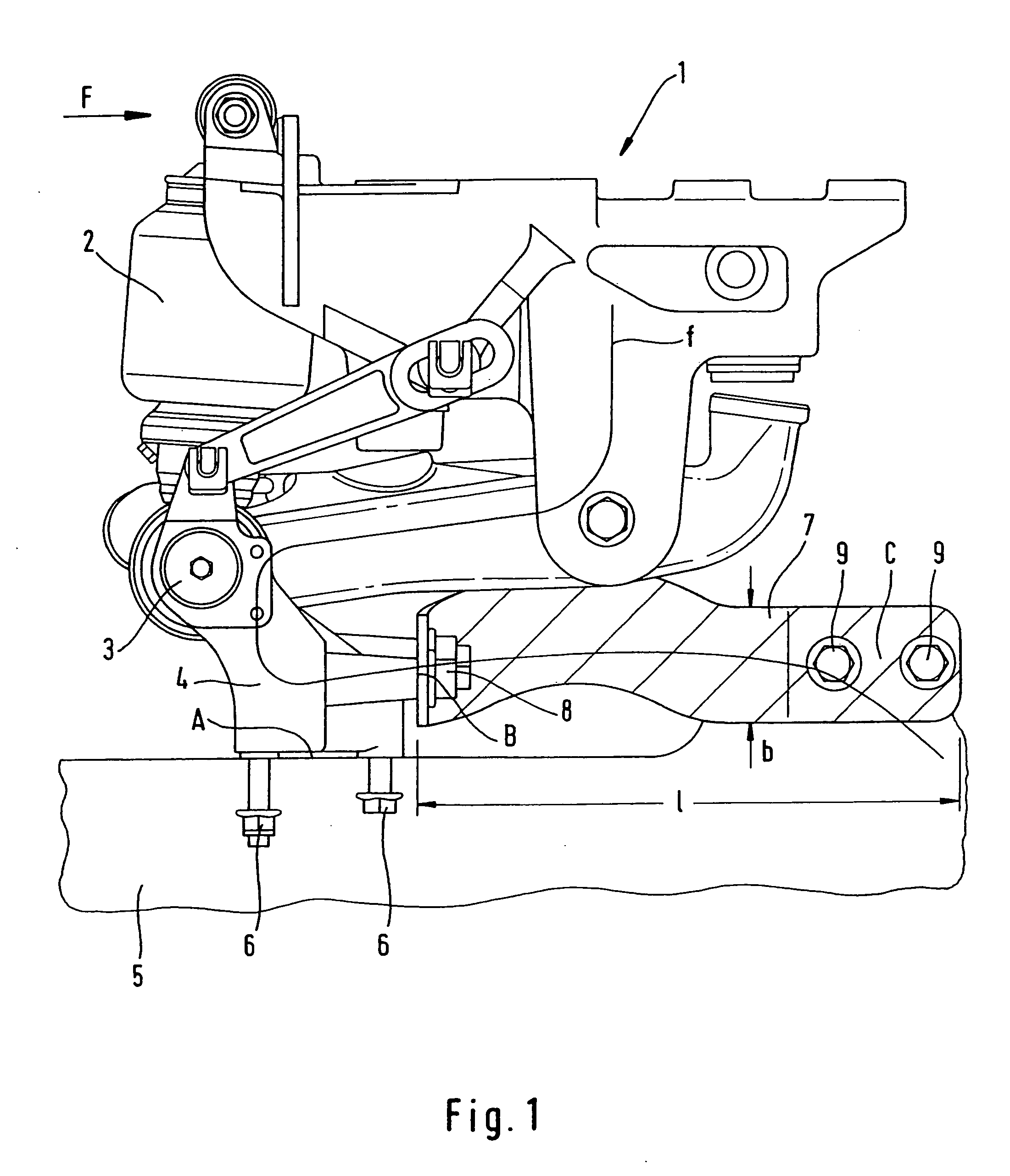
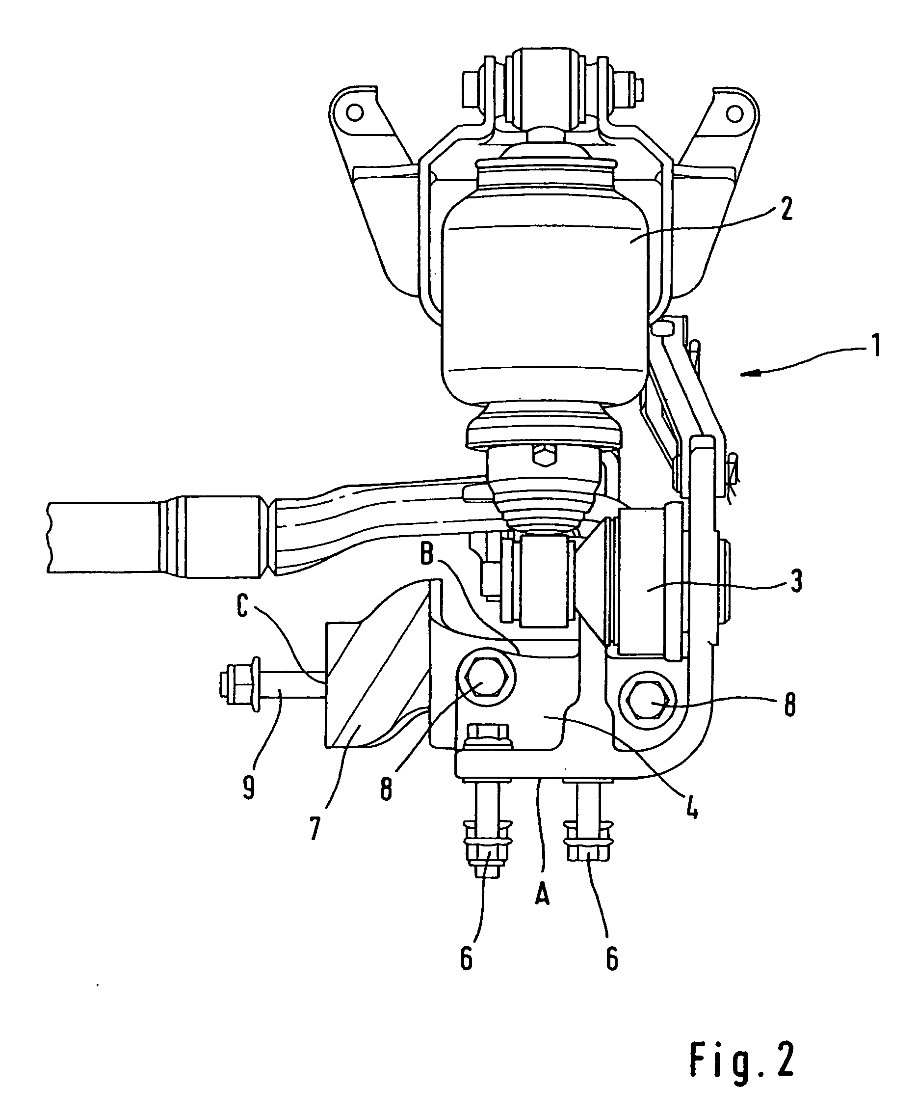
[0023]FIG. 1 depicts a retainer according to this invention. Two such retainers are usually provided in a vehicle, one on each side of the cab. In FIGS. 1 and 3, the left-hand side of the illustration points toward the front of the vehicle; the illustrations in FIGS. 2 and 4 represent the left-hand retainer of the cab as viewed from the front.

[0024] The retainer includes a support assembly 1. The support assembly incorporates, among other components, a spring-loaded leg 2. The bottom end of the spring-loaded leg features a pivot bearing 3 by way of which the cab is attached in tiltable fashion. The support assembly is not depicted in more detail since it is of a conventional design and is not a relevant factor in the invention.

[0025] Through junction A at its lower end, the support 1 is attached to a connecting element 4. This connecting element 4 attaches the support to a vehicle frame 5, which in FIGS. 1 and 3 is schematically outlined only. In the example shown, the connecting ...


PUM


Abstract

A retainer is created between the driver's cab and the frame of a vehicle with a spring-loaded support that permits the displacement of the driver's cab, and with a connecting element by way of which the driver-side support connects to the frame. In order for such retainer to ensure highest possible occupant safety as well as the safety of third parties while permitting low-cost production, a catch plate having one end is attached to the connecting element and its other end is attached to the frame is proposed.

Description

BACKGROUND AND SUMMARY OF THE INVENTION [0001] This invention relates to a retainer between a driver's cab and the frame of a vehicle. [0002] Vehicle safety has become an important objective in the design of commercial vehicles. One of the major aspects is the configuration of the retainer between the driver's cab and the frame of the vehicle. An analysis of actual accident history shows that the accidents that require critical attention in the design of a driver's cab and the associated cab support typically involve the rear-ending of another truck. The situation is particularly serious when the frame or chassis systems of the colliding vehicles extend at different levels, since in any such case the energy of the impact is not channeled directly into the frame system of either vehicle but instead strikes the components above and / or below the frame. A direct transfer of the impact energy into the frame system is the exception rather than the rule. A driver's cab takes a particular p...

Claims


Application Information

Patent Timeline
IPC IPC(8): B62D21/02B62D21/15B62D33/067
CPCB62D21/02B62D21/15B62D33/067
Inventor BOLLINGER, WALTERMCKELLIP, SPENCERRUEHLE, MARKUS
Owner DAIMLER AG
Why Eureka
Try Eureka