

Antenna and mobile wireless equipment using the same
- Summary
- Abstract
- Description
- Claims
- Application Information
AI Technical Summary
Benefits of technology
Problems solved by technology
Method used
Image

Examples
first embodiment
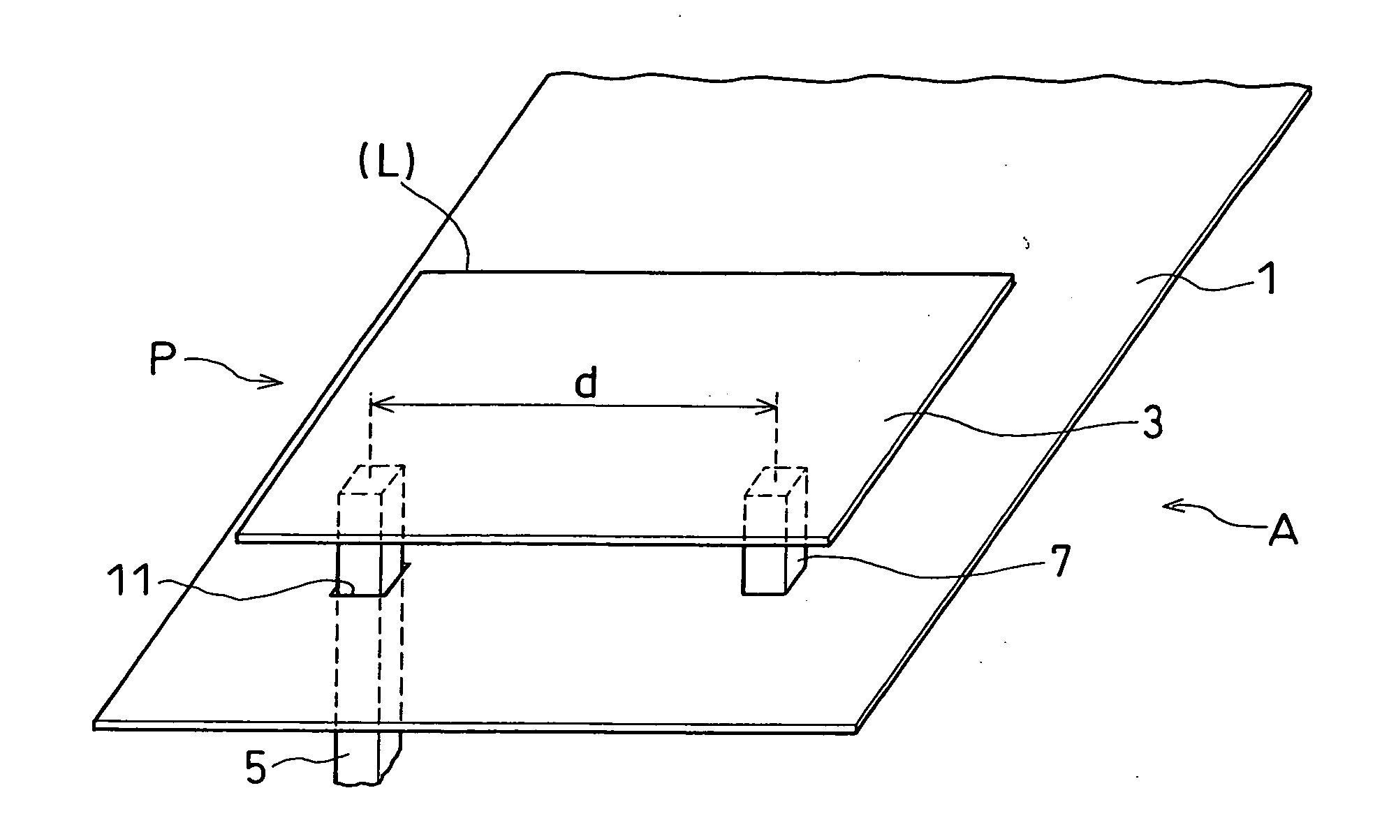
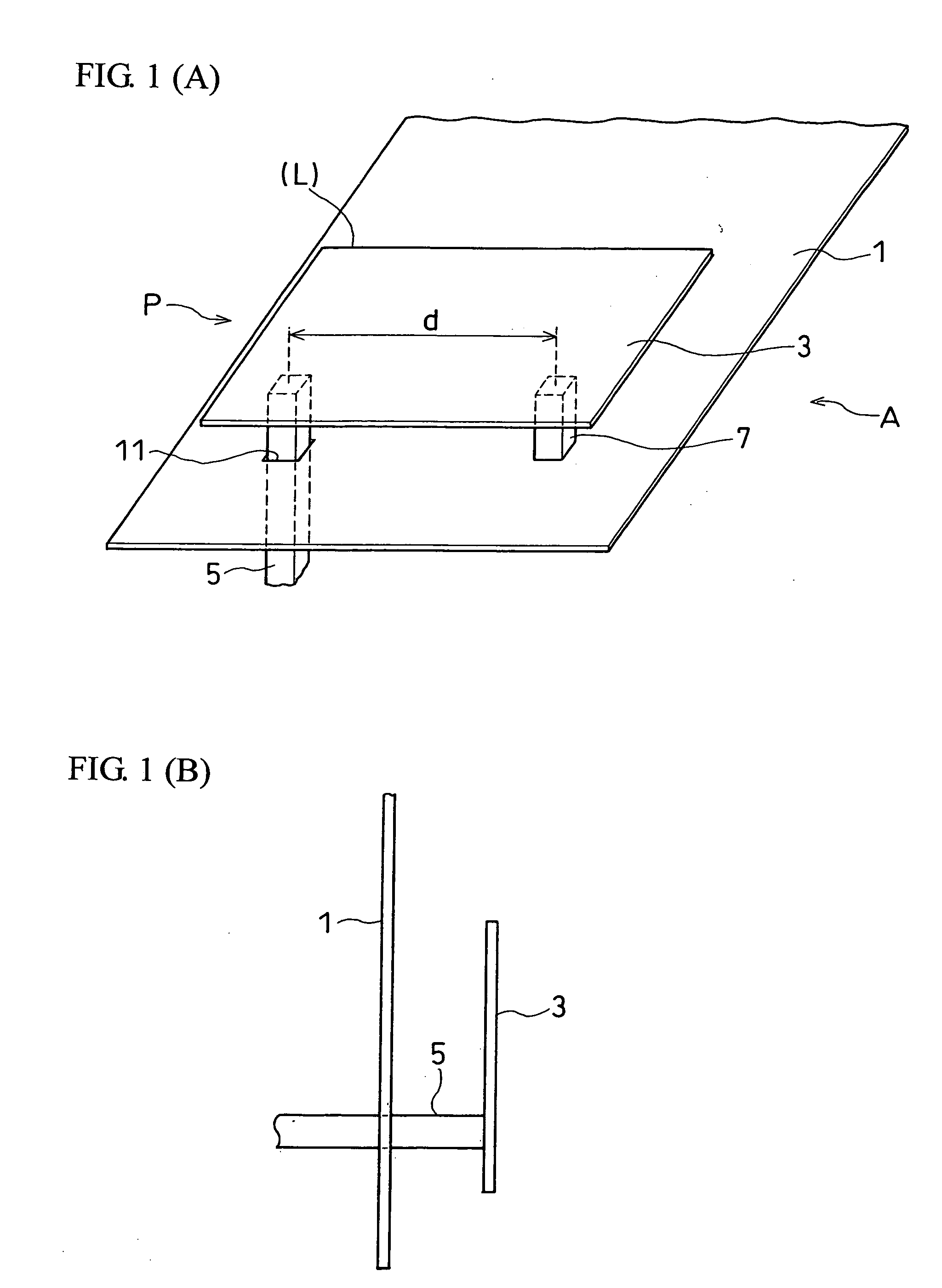
[0031] In the following, an antenna apparatus according to the present invention is described with reference to the drawings. FIG. 1 shows an example of the configuration of the antenna apparatus according to the present embodiment. FIG. 1(A) shows a perspective view and FIG. 1(B) shows a side view. As shown in FIG. 1(A) and FIG. 1(B), an antenna apparatus A according to the present embodiment comprises a tabular ground conductor 1, a radiation conductor 3 disposed in a location facing the ground conductor 1, a short-circuit portion 7 for short-circuiting the ground conductor 1 and the radiation conductor 3, an opening 11 disposed on the ground conductor 1 where the location is positioned at a distance of d from the short-circuit portion 7 in the in-plane direction of the tabular ground conductor 1, and a feed portion 5 extending from the radiation conductor 3 and passing through the opening 11 so as to not be in contact with the ground conductor 1. These members are disposed in the...
fourth embodiment
[0047] An antenna apparatus according to the present invention is described with reference to the drawings. As shown in FIG. 11(A), in the present embodiment, a notch cutting is provided in the radiation conductor between the feed portion and the short-circuit portion, thereby adjusting the distance between a feed portion 87 and a short-circuit portion 85. The antenna apparatus according to the present embodiment comprising a ground conductor 81 and a radiation conductor 83 has a notch cutting portion 91 formed in an L-shaped manner from the top side of the radiation conductor 83 as shown in the drawings, which is formed in an area including a straight line that connects the feed portion 87 with the short-circuit portion 85. In such a configuration, the electrical length between the feed portion 87 and the short-circuit portion 85 is based on the length of reference L11 circling the notch cutting portion 91 rather than the length of the top side as shown in the drawings (reference L...
fifth embodiment
[0048] A mobile phone according to the present invention in which the antenna apparatus according to each of the aforementioned embodiments is used is described. FIG. 12 shows a side view of the mobile phone according to the present embodiment and also shows the internal configuration thereof. As shown in FIG. 12, a mobile phone 100 according to the present embodiment shows an example of the configuration of a folding type mobile phone where a first casing 101 and a second casing 103 are capable of folding such that the LCD display portion and the input operation portion are disposed face-to-face with a rotation axis 105 as an axis. A radiation conductor 101b or 103b is disposed on either a first circuit board 101a or a second circuit board 102b disposed on both the first casing 101 and the second casing 103, the radiation conductor extending from the vicinity of one end of the rotation axis 105 to the other end that comes away from the rotation axis 105 (in the drawing, the radiati...
PUM
 Abstract
Description
Claims
Application Information