Motor control circuit for supplying a controllable driving voltage

Inactive Publication Date: 2005-10-13
GLOBAL MIXED MODE TECH
View PDF8 Cites 15 Cited by
  • Summary
  • Abstract
  • Description
  • Claims
  • Application Information

AI Technical Summary

Benefits of technology

[0010] Conventionally, a pulse width modulation (PWM) technique is usually adopted to control the absolute value of the driving voltage applied to the motor. More specifically, in the situation where the NMOS transistor Q4 is turned on and the NMOS transistors Q2 and Q3 are turned off, the control signal G1 may be implemented by a PWM signal such that the ON time of the NMOS transistor Q1 is determined by the duty cycle of the PWM control signal G1, thereby controlling an average value of the driving voltage. However, the PWM technique inevitably induces excessive disturbances in the supply voltage source Vm and the driving voltage applied to the motor M. For the application which requires extremely precise control of the motor, the conventional PWM technique may cause several disadvantageous effects. Therefore, it is desired to provide a control circuit capable of supplying a low noise driving voltage to the motor M.
[0011] An object of the present invention is to provide a motor control circuit capable of controlling a polarity and an absolute value of the driving voltage for a motor.
[0012] Another object of the present invention is to provide a motor control circuit capable of keeping constant an absolute value of a driving voltage for a motor.
[0013] Still another object of the present invention is to provide a motor control circuit capable of suppressing noise of a driving voltage for a motor.
[0014] According to the present invention, a motor control circuit is provided for supplying a driving voltage to a motor. The driving voltage is applied between a first terminal and a second terminal of the motor. The motor control circuit includes: an H-bridge circuit, a voltage detection circuit, an error amplifier, a feedback circuit, and a state control circuit.
[0015] The H-bridge circuit has a first linear unit, a second linear unit, a first switching unit, and a second switching unit. The first linear unit and the first switching unit are together coupled to the first terminal. The second linear unit and the second switching unit are together coupled to the second terminal. The voltage detection circuit generates at least one voltage detection signal representative of the driving voltage of the motor. The error amplifier generates at least one error signal representative of a difference between the at least one voltage detection signal and a command voltage signal. The at least one error signal is electrically separate from the first and the second switching units. The feedback circuit is coupled to the error amplifier for receiving the at least one error signal so as to apply the at least one error signal selectively to the first or the second linear unit. The state control circuit synchronously controls the first and the second switching units and the feedback circuit.

Problems solved by technology

However, the PWM technique inevitably induces excessive disturbances in the supply voltage source Vm and the driving voltage applied to the motor M. For the application which requires extremely precise control of the motor, the conventional PWM technique may cause several disadvantageous effects.

Method used


Image

  • Motor control circuit for supplying a controllable driving voltage
  • Motor control circuit for supplying a controllable driving voltage
  • Motor control circuit for supplying a controllable driving voltage

Examples


Embodiment Construction

[0030] The preferred embodiments according to the present invention will be described in detail with reference to the drawings.

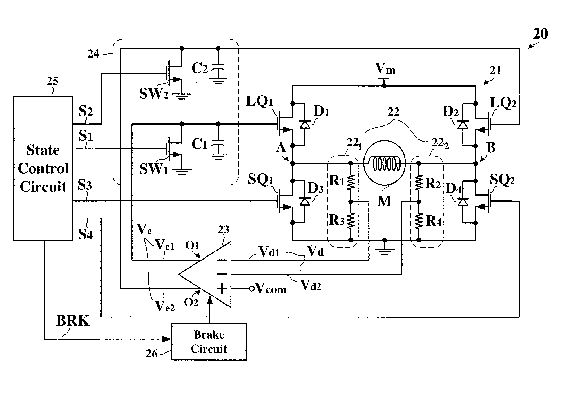
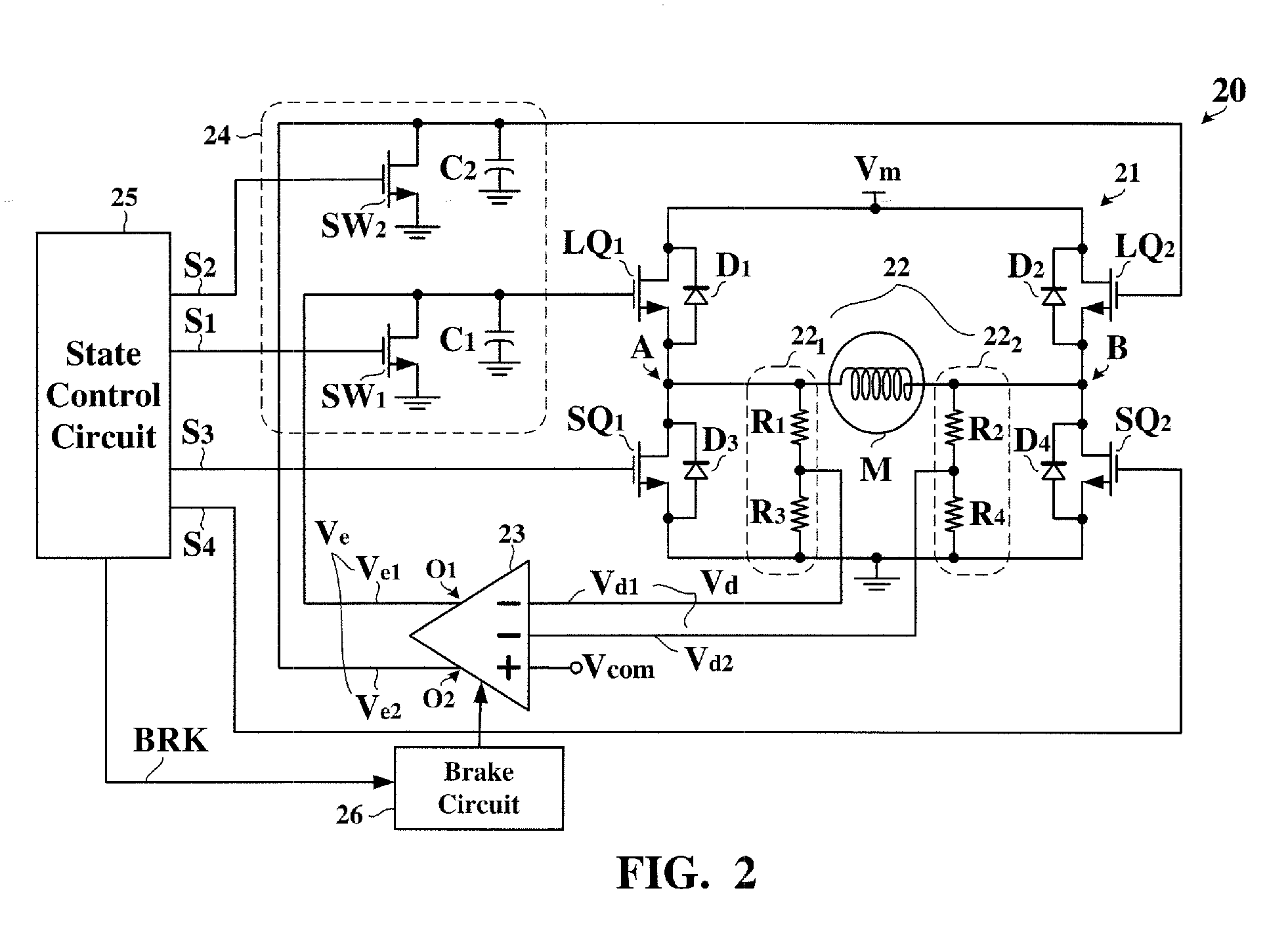
[0031]FIG. 2 is a circuit diagram showing an example of a motor control circuit 20 according to the present invention. Referring to FIG. 2, the motor control circuit 20 includes an H-bridge circuit 21, a voltage detection circuit 22, an error amplifier 23, a feedback circuit 24, and a state control circuit 25.

[0032] The H-bridge circuit 21 includes two linear units LQ1 and LQ2 and two switching units SQ1 and SQ2. The linear units LQ1 and LQ2 couple a supply voltage source Vm and a motor M while the switching units SQ1 and SQ2 couples the motor M and a ground potential. The linear units LQ1 and LQ2 may be operated in a linear mode, a conductive mode, and a nonconductive mode while the switching units SQ1 and SQ2 may be operated in the conductive mode and the nonconductive mode. The term “linear mode” refers to an operational state in which an equivalent res...


PUM


Abstract

For applying a driving voltage to a motor, an H-bridge circuit is constructed by a first and a second linear unit and a first and a second switching unit. An error amplifier generates an error signal representative of a difference between the driving voltage detected by a voltage detecting circuit and a command voltage signal. A state control circuit synchronously controls the first and second switching units and a feedback circuit. Through the feedback circuit, the error signal is selectively applied to the first or second linear unit such that one is operated in a linear mode and the other is operated in a nonconductive mode, thereby controlling the driving voltage to become proportional to the command voltage signal. The state control circuit further controls a brake circuit for transforming the error signal into a brake signal to operate the first and second linear units simultaneously in a conductive mode.

Description

BACKGROUND OF INVENTION [0001] 1. Field of the Invention [0002] The present invention relates to a motor control circuit and, more particularly, to a motor control circuit for supplying a controlling driving voltage to a motor. [0003] 2. Description of the Related Art [0004] Generally speaking, an H-bridge circuit constructed by four switch transistors may supply a driving voltage to a motor, such as DC motor, stepping motor, voice coil motor, and the like, for controlling a rotating direction, a rate of rotation, and other operational characteristics. [0005]FIG. 1 is a circuit diagram showing a conventional H-bridge circuit 10 for driving a motor M. Referring to FIG. 1, the motor M is coupled between a supply voltage source Vm and a ground potential through the H-bridge circuit 10. Although the motor M is in practice a complex system consisting of a variety of mechanical and electrical components, the driving voltage is essentially applied to a winding of the motor M for generating...

Claims


Application Information

Patent Timeline
CPCH02M3/1584H02M3/1588Y02B70/1466H02M2001/0045H02M2003/1555H02M2001/0012H02M1/0012H02M1/0045H02M3/1555Y02B70/10
Inventor CHEN, CHI-YANGCHEN, LI-CHENG
Owner GLOBAL MIXED MODE TECH
Why Eureka
Try Eureka