Phase correction element and optical head device

a phase correction element and optical head technology, applied in the field of phase correction elements and optical head devices, can solve the problems of large spherical aberration, inability to record and/or reproduce information, and difficulty in recording and/or reproducing information of these three types of optical disks by employing a single objective lens

Inactive Publication Date: 2005-10-13
ASAHI GLASS CO LTD
View PDF6 Cites 64 Cited by
  • Summary
  • Abstract
  • Description
  • Claims
  • Application Information

AI Technical Summary

Problems solved by technology

Accordingly, there has been a problem that in an optical head device for recording and/or reproducing an information, when an objective lens designed for any one type of optical disk is mounted for recording and/or reproducing an information from these optical disks compatibly, for example, when the optical head device is used for recording and/or reproducing an information from a different type of optical disk from the above type of optical disk, a large spherical aberration is generated and recording and/or reproducing of the information can not be performed.
However, as shown in the conventional examples 1 and 2, although there is an aperture-limiting element or a phase correction element applicable for recording and/or reproducing informations of two types of optical disks by employing a single objective lens, there is no phase correctio

Method used


Image

  • Phase correction element and optical head device
  • Phase correction element and optical head device
  • Phase correction element and optical head device

Examples


first embodiment

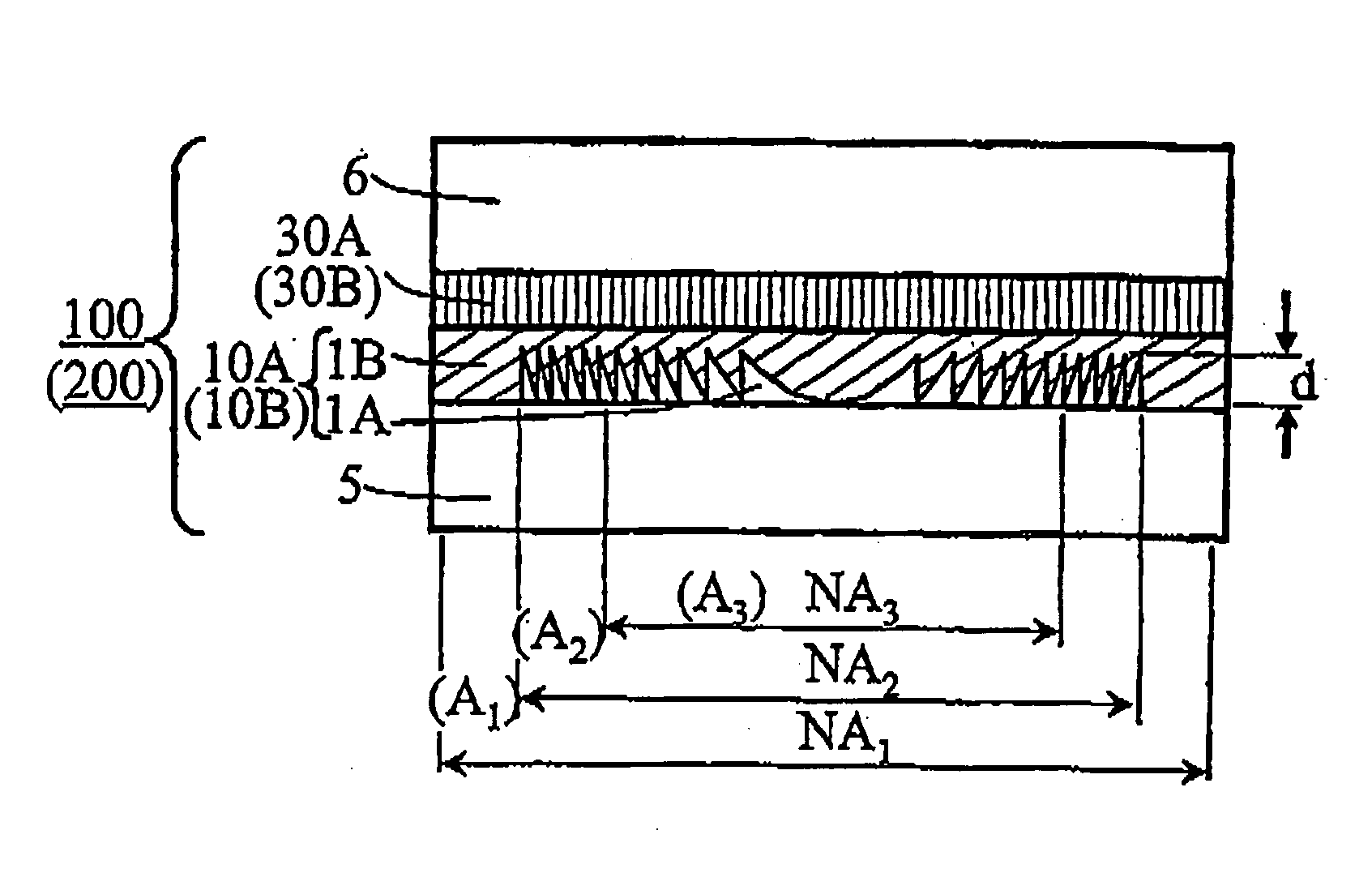
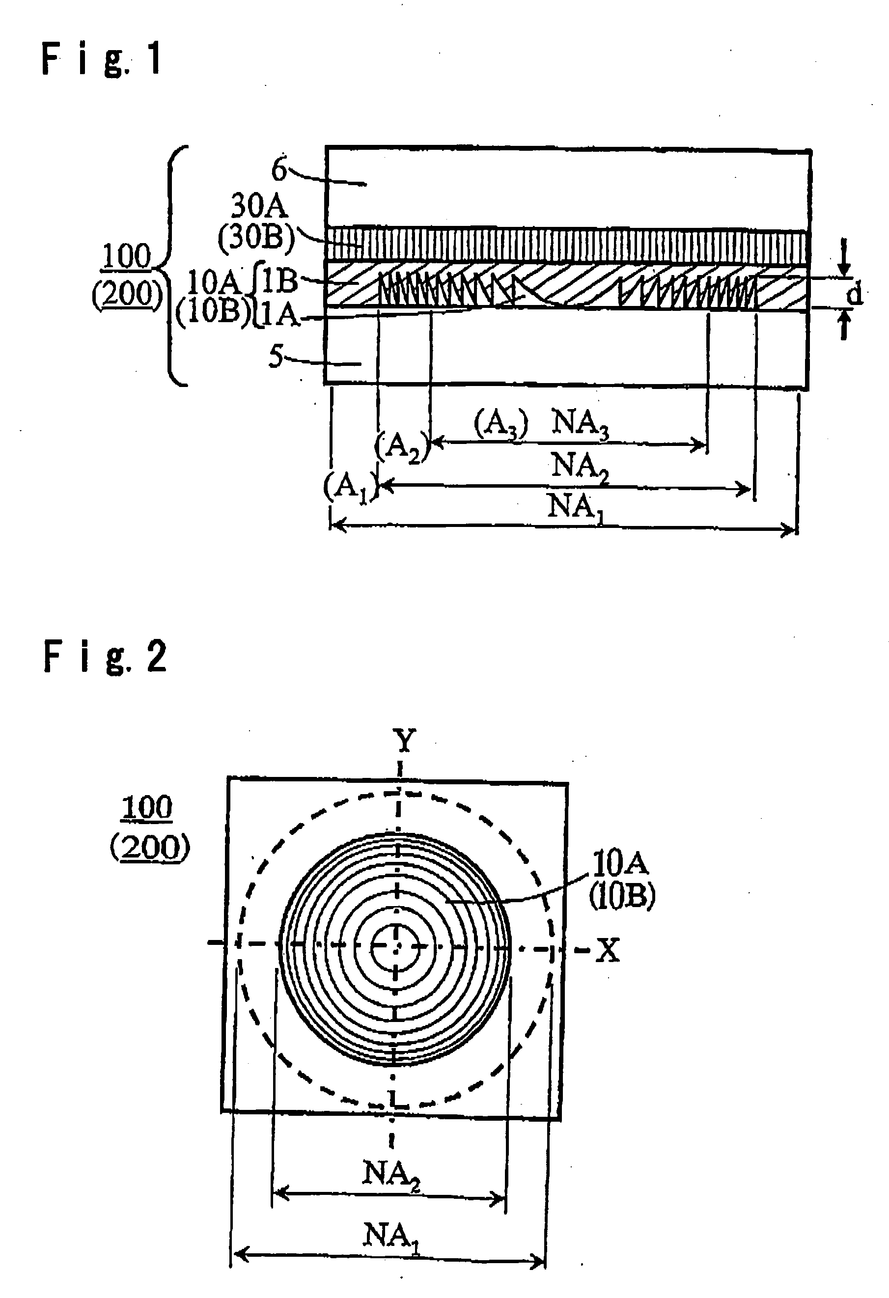
[0056]FIG. 1 is a cross-sectional view and FIG. 2 is a plan view showing an example of the construction of the first phase correction element according to the first embodiment of the present invention.

[0057] A first phase correction element 100 according to this embodiment is constructed by a first phase correction layer 10A and a first phase plate 30A each formed in a region of aperture NA2.

[0058] The first phase correction layer 10A is formed in an area of aperture NA2 corresponding to an optical disk for DVD in the effective diameter area of aperture NA1 corresponding to an optical disk for HD in the phase correction element. The first phase correction layer 10A comprises a transparent material (first transparent material) 1A having a refractive index of nA formed to have a saw-tooth-like concavo-convex portion having a cross-sectional shape of a saw-tooth-form (so-called blazed diffraction grating type) or a saw-tooth-form each of whose convex portions is approximated by a ste...

second embodiment

[0066] Then, a second phase correction element 200 shown in FIG. 1, comprising a first phase correction layer 10B constituted by transparent materials having different refractive index wavelength dispersions, namely a first transparent material 1A and a second transparent material 1B, and having a refractive index wavelength dispersion that the refractive index difference Δn is substantially zero at a wavelength of λ1 and a definite value at wavelengths of λ2 and λ3, and the first phase plate 30B, will be described as follows. Here, the first phase plate 30B has the same construction as the first phase plate 30A of the first phase correction element 100.

[0067] The transparent material 1A and the transparent material 1B are two types of materials having considerably different refractive index wavelength dispersion in a visible wavelength region, which have the same refractive index at a wavelength of λ1 and is transparent at wavelengths of λ1, λ2 and λ3 and may absorb light at other...

third embodiment

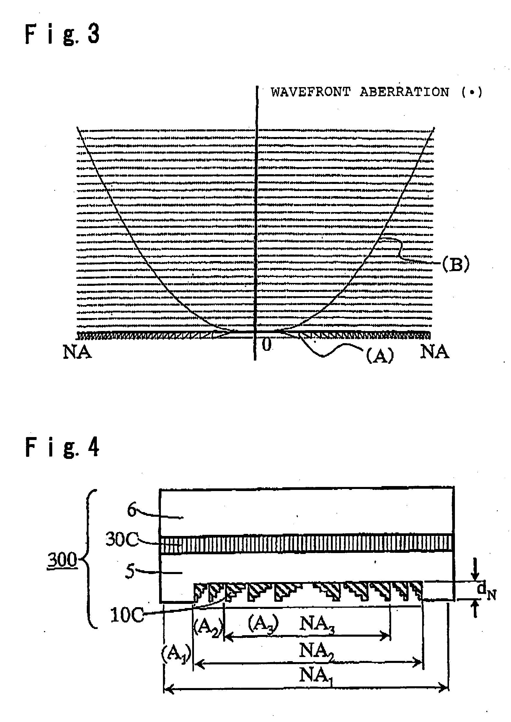
[0085] Then, FIG. 4 is a cross-sectional view showing the construction of a third phase correction element 300 according to another embodiment of the present invention.

[0086] Here, the plan view is the same as FIG. 2.

[0087] The phase correction element 300 according to this embodiment, comprises a first phase correction layer 10C formed in a region of numerical aperture NA2 on the surface of a transparent substrate 5 such as a glass, and a first phase plate 30C formed on one side of a transparent substrate 6 such as a glass. The first phase plate 30C has the same construction as the first phase plate 30A of the first phase correction element 100.

[0088] Here, in the same manner as the first phase correction layer 10B of the above second embodiment, the first phase correction layer 10C generates a wavefront aberration corresponding to (A) of FIG. 3 for incident light having a wavelength of λ2, and corrects a wavefront aberration shown in (B) of FIG. 3 generated when the third phase...


PUM


Abstract

The present invention provides a phase correction element which can be used for recording and/or reproducing an information of three types of optical disks for HD, DVD and CD by employing a single objective lens for HD, and an optical head device.
The phase correction element 100 of present invention comprises a first phase correction layer 10A formed in a region of numerical aperture NA2, and a first phase plate 30A integrally formed; the first phase correction layer 10A comprising a concavo-convex portion having a rotational symmetry with respect to the optical axis of incident light and having a cross-sectional shape of a saw-tooth-form or a saw-tooth-form whose convex portions are each approximated by a step form; the first phase plate 30A generating a birefringent phase difference of about an odd number times of π/2 for linearly polarized light having a wavelength of λ1; and the phase correction element 100 having a function of not changing a transmitted wavefront of the wavelength of λ1 and changing a transmitted wavefront of the wavelength of λ2 or transmitted wavefront of both wavelengths of λ2 and λ3 when three types of incident light in a λ1=410 nm wavelength band, a λ2=650 nm wavelength band and a λ3=780 nm wavelength band respectively, are incident.

Description

TECHNICAL FIELD [0001] The present invention relates to a phase correction element and an optical head device, particularly to a phase correction element to be employed for an optical head device to be used for recording and / or reproducing an information from three types of optical recording media employing different wavelengths, and to the optical head device. BACKGROUND ART [0002] Recently, as well known, various types of optical recording media for recording and / or reproducing information and optical head devices capable of recording and / or reproducing an information to the optical recording media have been developed and used. [0003] Among these, an optical recording medium (hereinafter referred to as “optical disk”) for CD is an optical disk having a cover thickness of 1.2 mm for protecting the information recording plane, and a semiconductor laser of a 780 nm wavelength band as a light source and an objective lens having an NA (numerical aperture) of from 0.44 to 0.51 are emplo...

Claims


Application Information

Patent Timeline
IPC IPC(8): G02B5/18G02B5/28G02B5/30G02B13/00G11B7/00G11B7/1275G11B7/135G11B7/1353G11B7/1367G11B7/1392
CPCG02B27/0037G02B27/4238G02B27/4261G11B2007/0006G11B7/1353G11B7/1367G11B7/13922G11B7/1275G02B5/30
Inventor OOI, YOSHIHARUMURAKAWA, MASAHIROSATO, HIROMASAMIYAMURA, MASAO
Owner ASAHI GLASS CO LTD
Why Eureka
Try Eureka