Automatic frequency correction PLL circuit

a technology of automatic frequency correction and circuit, which is applied in the direction of pulse generator, pulse technique, wireless commuication service, etc., can solve the problems of system becoming uncontrollable, difficult to design synchronization of the entire semiconductor, and fluctuation in the oscillating frequency due to this nois

Active Publication Date: 2005-10-13
MITSUBISHI ELECTRIC CORP
View PDF8 Cites 67 Cited by
  • Summary
  • Abstract
  • Description
  • Claims
  • Application Information

AI Technical Summary

Benefits of technology

[0022] As described above, in the automatic frequency correction PLL circuit according to the present invention, a digital control circuit is provided with a High-side comparator which receives an analog control voltage, a Low-side comparator, a state monitor circuit and a counter & decoder circuit, and especially at least one of the High-side comparator and Low-side comparator is provided with a threshold switching circuit which selectively gives a first threshold and second threshold which are different in magnitude, and when the threshold switching circuit gives the first threshold, if the analog control voltage remains between the High-side threshold and Low-side threshold, the threshold switching circuit switches the first threshold to the second threshold and expands the interval between the High-side threshold and Low-side threshold, and can thereby avoid unnecessary switching of offsets and provide a stable PLL operation.

Problems solved by technology

When this VCO gain is large, when, for example, noise is applied to a node of the control voltage, the fluctuation in the oscillating frequency due to this noise also increases.
In an on-chip PLL circuit which is a PLL circuit incorporating a voltage-controlled oscillator circuit formed on a semiconductor chip, the presence of large jitter in a clock causes the inconvenience of making it difficult to design synchronization of the entire semiconductor chip which constitutes the PLL circuit.
In this case, after the locking of the oscillating frequency is completed, if the operating temperature or supply voltage fluctuates, there is a danger of the system becoming uncontrollable because the analog control voltage is set to the upper limit or lower limit.
However, after the locking is completed, if the ambient temperature or supply voltage fluctuates producing a frequency error exceeding the digital adjustment unit using the digital control circuit, the digital control circuit responds to it, which may cause the oscillating frequency to change non-consecutively or discretely in response to the variation of the digital control signal (Digital Control).
However, prior art 2 also has another problem as shown below.
Furthermore, according to prior art 2, once the setting is completed, the digital control circuit is fixed thereafter, and so after the locking of the PLL circuit is completed, even if the setting of the oscillating frequency by the digital control circuit becomes no longer optimal due to a variation in the operating environment such as ambient temperature or secular variation, etc., it is not possible to perform readjustment.
However, another problem occurs as shown below.
Thereafter, the stable state changes as indicated by a white bullet in FIG. 14, but the operation becomes unstable during an offset switching period.

Method used


Image

  • Automatic frequency correction PLL circuit
  • Automatic frequency correction PLL circuit
  • Automatic frequency correction PLL circuit

Examples


first embodiment

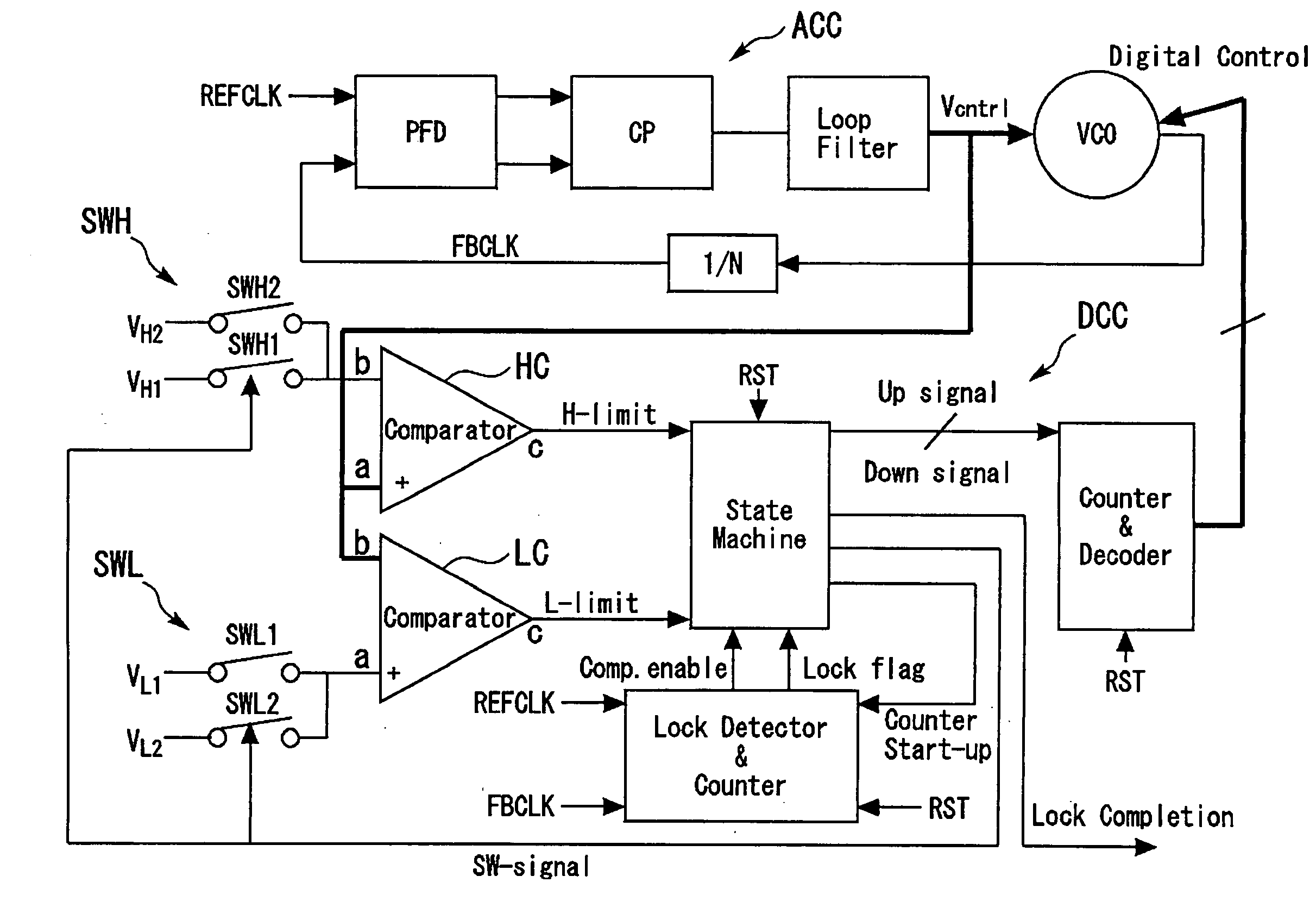
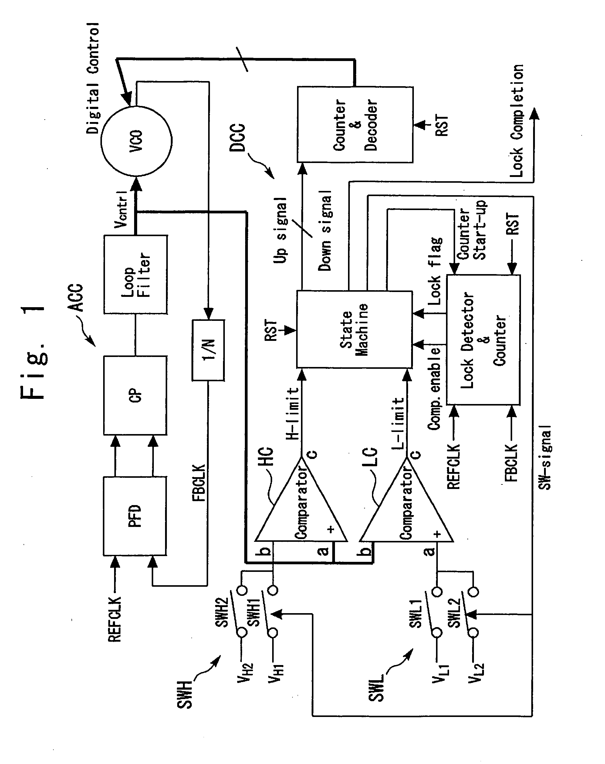
[0038]FIG. 1 is a block diagram showing First Embodiment of an automatic frequency correction PLL circuit according to the present invention. The automatic frequency correction PLL circuit according to this First Embodiment includes a voltage-controlled oscillator circuit VCO, an analog control circuit ACC for this voltage-controlled oscillator circuit and a digital control circuit DCC. The analog control circuit ACC generates an analog control voltage (Vcntrl) and the digital control circuit DCC generates a digital control signal (Digital Control), to control the frequency of the voltage-controlled oscillator circuit VCO.

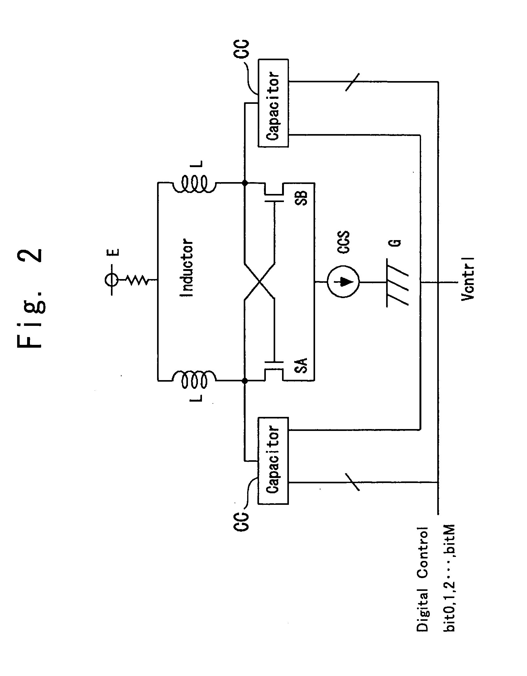
[0039]FIG. 2 shows the internal structure of the voltage-controlled oscillator circuit VCO. The voltage-controlled oscillator circuit VCO is provided with a pair of inductors L, a pair of switches SA, SB which perform switch operations opposite to each other and a pair of capacitor circuits CC. The switches SA, SB are, for example, MOS transistors and connected in...

second embodiment

[0071]FIG. 5 shows Second Embodiment of an automatic frequency correction PLL circuit according to the present invention. First Embodiment is constructed in such a way that High-side thresholds VH1, VH2 are selectively given to the High-side comparator HC and Low-side thresholds VL1, VL2 are selectively given to the Low-side comparator LC, while in this Second Embodiment, one High-side threshold VH2 is given to the High-side comparator HC fixedly. As in the case of First Embodiment, Low-side thresholds VL1, VL2 are selectively given to the Low-side comparator LC by a switch signal (SW Signal) from the state monitor circuit (State Machine). According to this structure, in Second Embodiment, only a down signal is given from the state monitor circuit (State Machine) to the counter & decoder and the up signal is not given. The rest of the structure is the same as that in First Embodiment.

[0072]FIG. 6 shows a flow chart of the state monitor circuit (State Machine) in this Second Embodim...

third embodiment

[0086] This Third Embodiment uses a capacitor circuit CC shown in FIG. 7 instead of the capacitor circuit CC shown in FIG. 3 for the capacitor circuit CC in First Embodiment. It is also possible to use the capacitor circuit CC shown in FIG. 7 for the capacitor circuit CC in Second Embodiment instead of the capacitor circuit CC shown in FIG. 3.

[0087] In the capacitor circuit CC shown in FIG. 7, the analog control capacitance section CA is constructed of a varactor VAa which is a variable capacitor and one end of this varactor VAa is connected to an inductor L and an analog control voltage (Vcntrl) is given to the other end. Suppose the capacitor of this varactor VAa is Cx and the maximum value is Cxmax.

[0088] Varactors VA0, VA1, . . . , VAM which are variable capacitors are also used for the digital control capacitance section CD. One end of each varactor is connected to the inductor L and the other end is connected to switches s1, s2 controlled by their respective bits of the digi...


PUM


Abstract

An automatic frequency correction phase-locked loop (PLL) circuit includes an analog control circuit and a digital control circuit. The digital control circuit includes a High-side comparator and a Low-side comparator which receive an analog control voltage, a state monitor circuit, and a counter and decoder circuit. At least one of the High-side comparator and the Low-side comparator includes a threshold switching circuit which selectively gives a first threshold and a second threshold having different. When the analog control voltage remains between the High-side threshold and the Low-side threshold in a state in which the threshold switching circuit gives the first threshold, the threshold switching circuit switches the first threshold to the second threshold and expands the interval between the High-side threshold and the Low-side threshold.

Description

BACKGROUND OF THE INVENTION [0001] 1. Field of the Invention [0002] The present invention relates to an automatic frequency correction PLL circuit provided with a voltage-controlled oscillator circuit (VCO) having the function of automatic oscillating frequency correction function which detects and automatically corrects an oscillating frequency deviation of this voltage-controlled oscillator circuit. [0003] 2. Background Art [0004] In a PLL circuit incorporating a voltage-controlled oscillator circuit, the oscillating frequency of the voltage-controlled oscillator circuit fluctuates due to variations in manufacturing processes, fluctuations in a supply voltage or ambient temperature during operation. To compensate for the fluctuations in this oscillating frequency, it is a general practice to set a wide range of the oscillating frequency beforehand. In this case, the ratio of fluctuation in the oscillating frequency to fluctuation in a control voltage of the voltage-controlled osci...

Claims


Application Information

Patent Timeline
Patent Type & Authority Applications(United States)
IPC IPC(8): H03L7/095H03B5/12H03L7/099H03L7/10H03M1/12
CPCH03L7/10H03L7/099H03L7/104H03L7/113
Inventor YOSHIMURA, TSUTOMU
Owner MITSUBISHI ELECTRIC CORP
Why Eureka
Try Eureka