
Composite model construction and method

a composite model and construction method technology, applied in the direction of toys, remote-control toys, toy aircrafts, etc., can solve the problems of high cost, high degree of scale fidelity, and difficult to achieve the effect of improving the solution of model construction and use, quick and easy construction of a model

Inactive Publication Date: 2005-10-13
KLOOS WADE M
View PDF34 Cites 17 Cited by
  • Summary
  • Abstract
  • Description
  • Claims
  • Application Information

AI Technical Summary

Benefits of technology

[0011] The thin, semi-rigid plastic shell components used in the present model construction also provide a limited degree of resilience in the event of impact, but are sufficiently rigid and sturdy to accept permanently-formed detail molding therein, e.g., simulated panel seams, rivet lines, etc. A modeler may quickly and easily construct a model having a high degree of scale fidelity using the present model construction system. Yet, the materials may be patched and repaired to some extent if damaged, or entire shell components may be replaced as required. This assemblage of resilient plastic foam and flexible plastic outer shell provides improved solutions in model construction and use, specifically increased durability, simplicity of scale replication, and ease of repair.

Problems solved by technology

However, such traditional construction methods are quite time consuming, with the average total flight or operating time of a model being considerably shorter than the required building time.
While such material is light in weight, it has numerous disadvantages in model construction.
Polystyrene foam plastic is relatively brittle, and is subject to serious impact damage when used in operating models.
Moreover, the porous material does not accept a fine finish, and requires covering with other materials in order to provide a realistic and aerodynamic finished model.
However, it can be somewhat tedious to apply, in that it can be difficult to work around compound curves and requires a heating iron to soften the adhesive backing and shrink the material during the process to provide a taut covering.
Even then, the finish is unsuitable for scale models (i.e. those models that replicate, in miniature, full size vehicles), as no scale panel seams, rivet lines, rib stitching, etc. may be formed in such a covering or coating without extensive additional labor, and the glossy finish may not be suitable for many scale models.
Also, while the material is relatively durable, it is not completely resistant to punctures and tears, does nothing to protect the underlying structure from damage in the event of a hard impact, and requires frequent maintenance.

Method used


Image

  • Composite model construction and method
  • Composite model construction and method
  • Composite model construction and method

Examples


Embodiment Construction

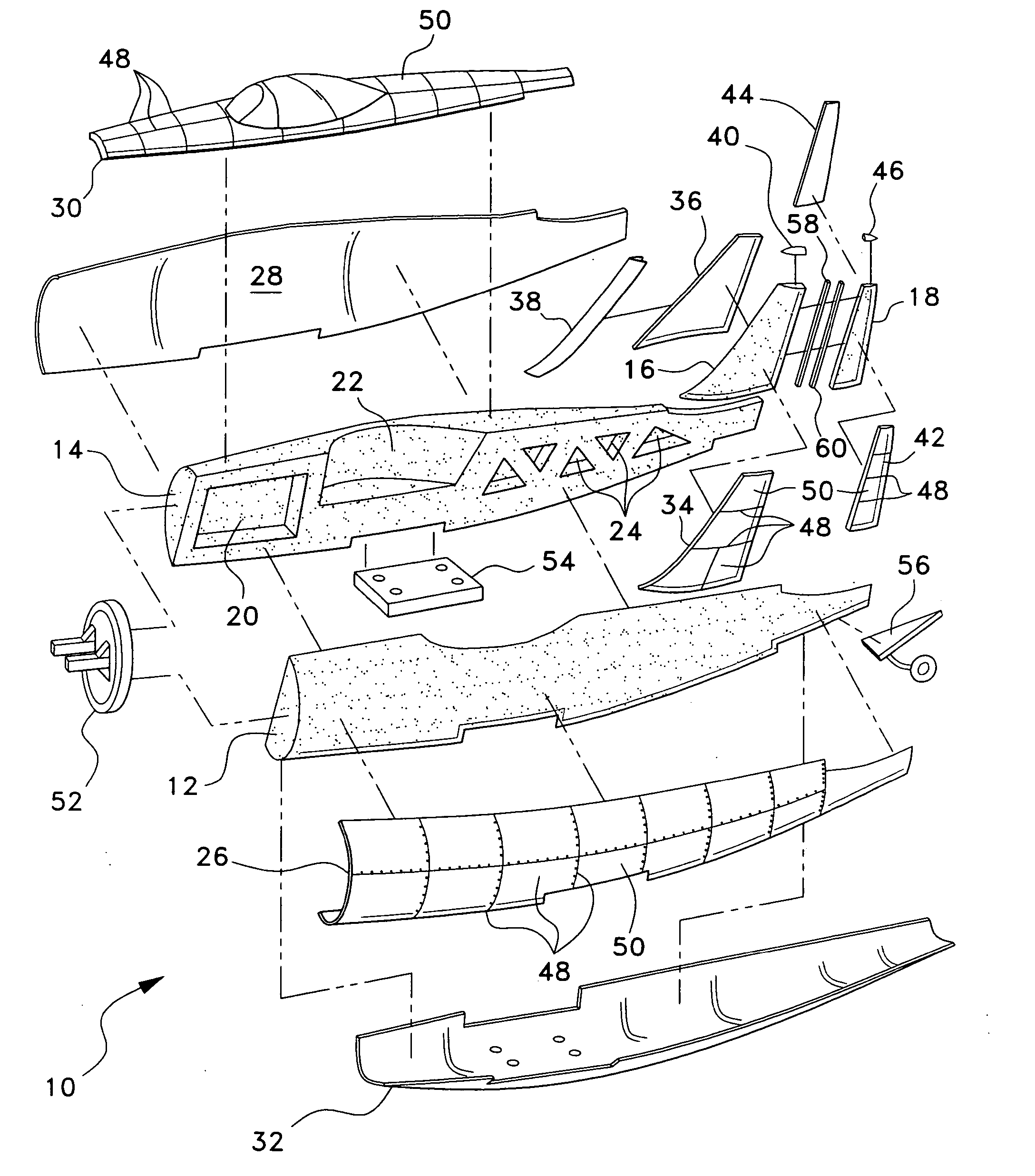
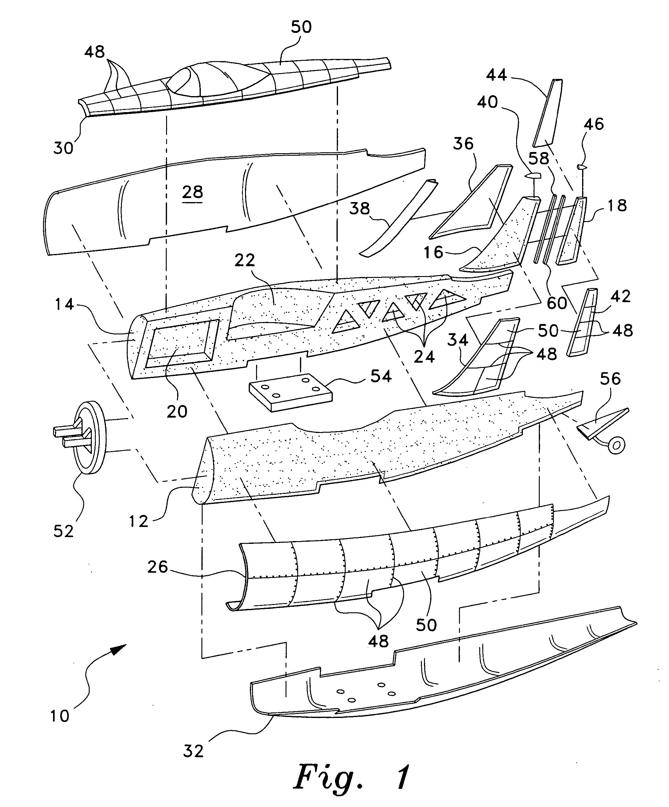
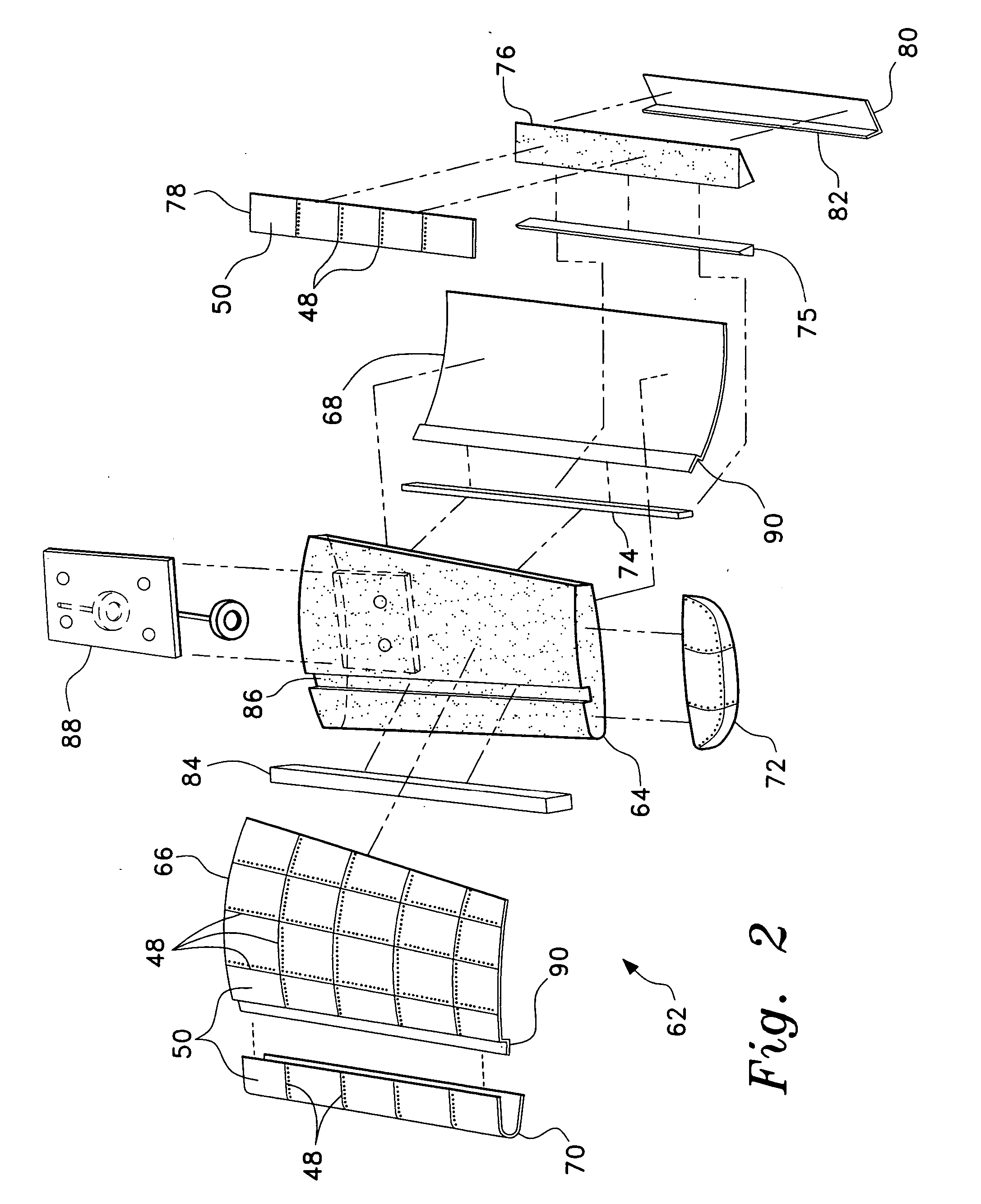
[0021] The present invention comprises various embodiments of a model or miniature vehicle, a kit for the assembly thereof, and a method of manufacturing such a kit. While the miniature vehicle may be a model aircraft, as shown in FIGS. 1 through 5, it will be seen that the present invention lends itself to application to miniature or model boats and cars as well.

[0022]FIG. 1 of the drawings provides an exploded perspective view of the fuselage and vertical empennage structure 10 of a model airplane kit or assembly according to the present invention, with FIG. 4 providing an elevation view in section of the completed fuselage structure 10 and FIG. 5 providing a perspective view of an exemplary model or miniature aircraft constructed in accordance with the present invention. The composite model construction provides for the use of a resilient foam plastic material, e.g., expanded polypropylene (EPP) foam, for the core components, i.e., left and right fuselage halves 12 and 14, the v...


PUM


Abstract

The composite model construction uses a semi-flexible expanded polypropylene foam plastic core with a thin, semi-rigid polycarbonate plastic shell adhesively attached to the core. The core includes various rigid structural members installed therein, as required, for sufficient structural stiffness for the model. The core and plastic shell components may be formed by injection molding, vacuum forming, or other processes. The model construction method provides a highly accurate outer surface for a model, with the outer shell being formed with scale details, such as panel seams, rivet lines, etc. during the molding or forming process. A motor or other prime mover may be added to the composite model body. The materials used in the composite model are resilient with a flexible yet tough outer shell to resist impact damage, and allow repairs to be made quickly and easily when required.

Description

CROSS-REFERENCE TO RELATED APPLICATION [0001] This application claims the benefit of U.S. Provisional Patent Application Ser. No. 60 / 536,906, filed Jan. 16, 2004.BACKGROUND OF THE INVENTION [0002] 1. Field of the Invention [0003] The present invention relates generally to miniature model vehicle construction methods and materials. More specifically, the present invention comprises the use of reinforced non-rigid foam plastic material for the core of a model structure, with a thin, preformed, semi-rigid plastic sheet material used to cover the foam core with its reinforcements. [0004] 2. Description of the Related Art [0005] Miniature models, particularly flyable aircraft models, have conventionally been constructed of relatively lightweight materials using much the same componentry as in full-scale aircraft. While weight is not so critical in model boats and cars, it is still of some concern in that better performance is achieved with lighter weight vehicles. However, such tradition...

Claims


Application Information

Patent Timeline
Patent Type & Authority Applications(United States)
IPC IPC(8): A63H17/00A63H27/00A63H30/04A63H33/00
CPCA63H17/002A63H30/04A63H27/001
Inventor KLOOS, WADE M.
Owner KLOOS WADE M
Learn More