Methods and systems for tracking signals with diverse polarization properties

a tracking signal and polarization technology, applied in the direction of polarised antenna unit combination, transmission monitoring, instruments, etc., can solve the problems of unstable tracking performance, performance degradation, and incident field matching the design polarization of a given antenna not always received, so as to reduce system sensitivity and avoid or lessen this unstable operation

Active Publication Date: 2005-10-13
THE AEROSPACE CORPORATION
View PDF9 Cites 7 Cited by
  • Summary
  • Abstract
  • Description
  • Claims
  • Application Information

AI Technical Summary

Benefits of technology

[0013] Two problems therefore are faced when the received signals have mixed and time-varying polarization properties. The first problem is the signal reduction that results from polarization mismatch, which in turn, results in a reduction in system sensitivity. The second problem is the degradation in antenna tracking performance and possible loss of antenna tracking resulting from the unstable behavior. It would be desirable to be able to provide a method that avoids or lessens this unstable operation and results in antenna tracking that is insensitive to the polarization of received signals.

Problems solved by technology

However, in practice, incident fields matching the design polarization for a given antenna are not always received.
While such antenna tracking techniques perform very well when the incident signals have the design polarization characteristics, performance degrades when the incident polarization is cross-polarized with the design polarization.
The cross polarized signal can result in unstable tracking performance and the antenna failing to track the desired signal.
When the antenna receives a cross polarized signal, the difference over sum ratio of the tracking output of the antenna no longer has the desired linear variation as the antenna position deviates from the antenna beam axis.
Thus, the antenna response is unstable when tracking the cross polarized signal.
Such an approach, however, requires the selection of the appropriate signal polarization and since either orthogonal polarization is not matched to the incident signal, loss of signal power occurs.
In summary, tracking performance is degraded by polarization mismatch loss, and antenna tracking can become very unstable when the received signal is predominately cross-polarized.
Cross-polarized signals do not have this expected linear response resulting in unstable tracking behavior.
Two problems therefore are faced when the received signals have mixed and time-varying polarization properties.
The first problem is the signal reduction that results from polarization mismatch, which in turn, results in a reduction in system sensitivity.
The second problem is the degradation in antenna tracking performance and possible loss of antenna tracking resulting from the unstable behavior.

Method used


Image

  • Methods and systems for tracking signals with diverse polarization properties
  • Methods and systems for tracking signals with diverse polarization properties
  • Methods and systems for tracking signals with diverse polarization properties

Examples


Embodiment Construction

[0023] The following is a detailed description for carrying out the invention. This description is not to be taken in a limiting sense, but is made merely for the purpose of illustrating the general principles of the invention.

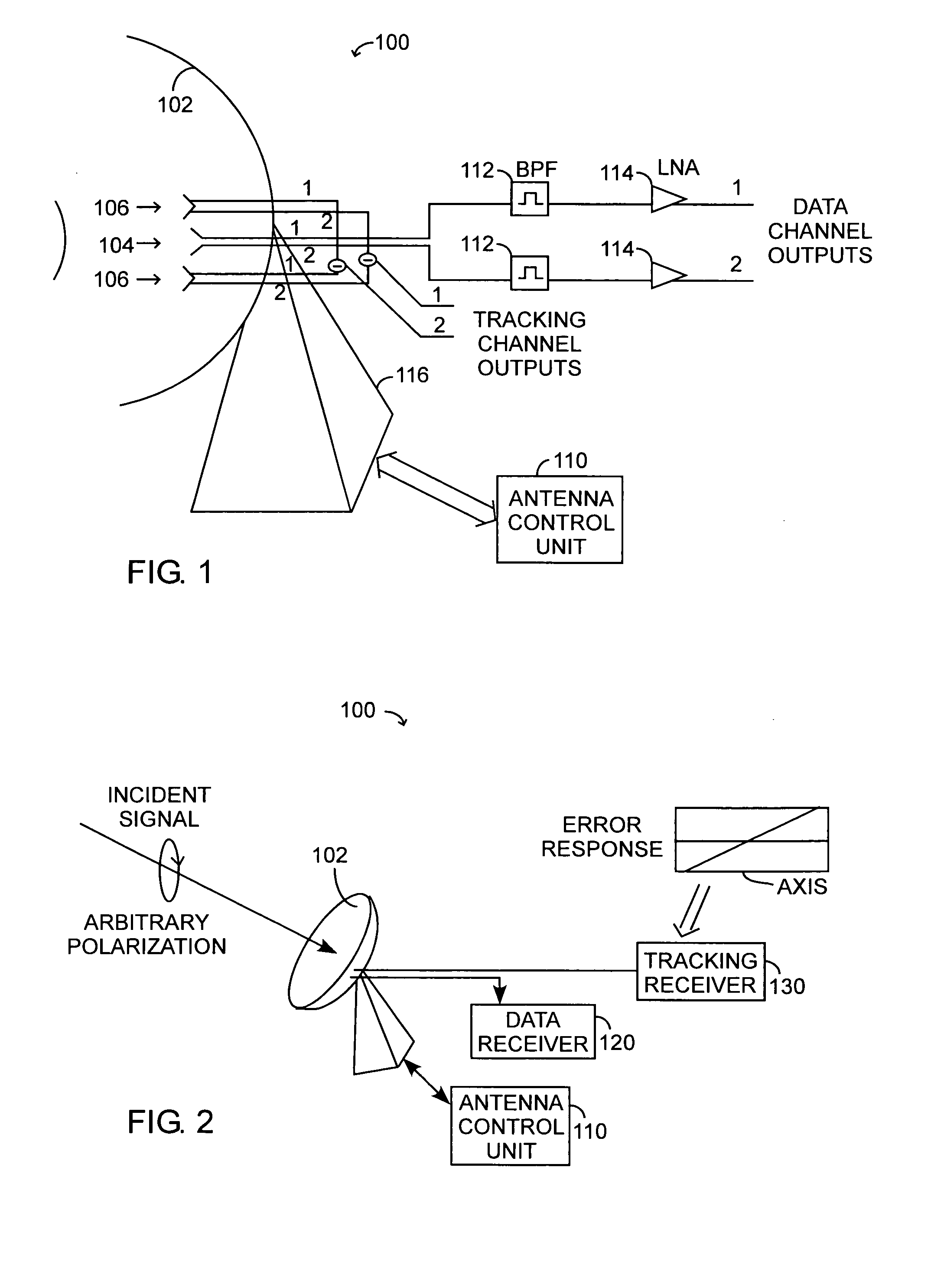
[0024] The present invention generally involves methods and systems for tracking signals that have diverse polarization properties. Referring to FIG. 1, an antenna system 100 according to an example embodiment of the present invention includes a reflector antenna 102, a central feed 104, tracking feeds 106, an antenna control unit (ACU) 110, band pass filters 112, low noise amplifiers 114 and a positioner 116, configured as shown. The example antenna system 100 has a tracking feed design that is configured to provide orthogonally polarized terminals for both data and tracking channels. A reflector antenna with a Cassegrain configuration, by way of example, provides high gain performance with an associated narrow beamwidth and uses a closed loop tracking syste...


PUM


Abstract

Methods and systems for tracking signals with diverse polarization properties address both sensitivity and antenna tracking performance issues. In one embodiment, complex weightings for matching a polarization of an incident signal on a data channel are determined, and the complex weightings are applied to a tracking channel such that an antenna system polarization is matched to the polarization of the incident signal. In another embodiment, orthogonally polarized tracking channel components of an incident signal are processed to make a determination as to which of the orthogonally polarized tracking channel components is stronger, and this determination is used to select a polarization of a data channel to reduce a polarization mismatch loss.

Description

STATEMENT OF GOVERNMENT INTEREST [0001] The invention was made with Government support under National Oceanic & Atmospheric Administration (NOAA) Contract 50-SPNA-0-00012. The Government has certain rights in the invention.BACKGROUND OF THE INVENTION [0002] Radio frequency signals received by antennas have polarization properties that characterize the orientation of the incident electric fields. Communication systems antennas are generally designed to receive radio frequency signals having a specified polarization. However, in practice, incident fields matching the design polarization for a given antenna are not always received. If the polarization of the incident field approximates the polarization of the antenna, most of the signal power is received by the antenna, and the difference between the ideal and actual polarization is characterized by “polarization loss.”[0003] When such communication systems require narrow beamwidth antennas for signal reception, the antennas must be ac...

Claims


Application Information

Patent Timeline
Patent Type & Authority Applications(United States)
IPC IPC(8): H04B7/10
CPCH04B7/10
Inventor DYBDAL, ROBERT B.PIDHAYNY, DENNY D.
Owner THE AEROSPACE CORPORATION
Why Eureka
Try Eureka