Percutaneous transluminal angioplasty device with integral embolic filter

a transluminal angioplasty and filter technology, applied in the field of surgical devices, can solve the problems of adverse clinical symptoms, adverse clinical consequences, and reduce the blood flow to the organs

Active Publication Date: 2005-10-13
CONTEGO MEDICAL
View PDF23 Cites 82 Cited by
  • Summary
  • Abstract
  • Description
  • Claims
  • Application Information

AI Technical Summary

Benefits of technology

[0009] Stated generally, the present invention comprises a percutaneous transluminal angioplasty device with integral embolic filter. Because the filter is integral with the catheter of the angioplasty device, there is no need to insert a separate device into the vessel. Further, proper placement of the angioplasty balloon assures proper placement of the embolic filter.

Problems solved by technology

If plaque builds up in these vessels, blockages can develop, reducing blood flow to the organs and causing adverse clinical symptoms, up to and including fatality.
These embolic particles can result in adverse clinical consequences.
These devices are also prone to releasing embolic particles downstream from the stenosed location.
These embolic protection guidewires also have flexibility and stability problems that make the protected angioplasty procedure difficult in many cases.
In the case of saphenous vein grafts, the problems relate specifically to aorto-ostial lesions, where the guidewire may not be long enough to provide Is support, or distal vein graft lesions, where there is not enough of a landing zone for the filter.
The latter is a problem as currently available filter systems have a considerable distance between the treatment balloon and the distal filter.
This distance is a problem not only in distal vein graft lesions, but also in arterial stenoses in which there is a side branch immediately after the stenosis.

Method used


Image

  • Percutaneous transluminal angioplasty device with integral embolic filter
  • Percutaneous transluminal angioplasty device with integral embolic filter
  • Percutaneous transluminal angioplasty device with integral embolic filter

Examples


Embodiment Construction

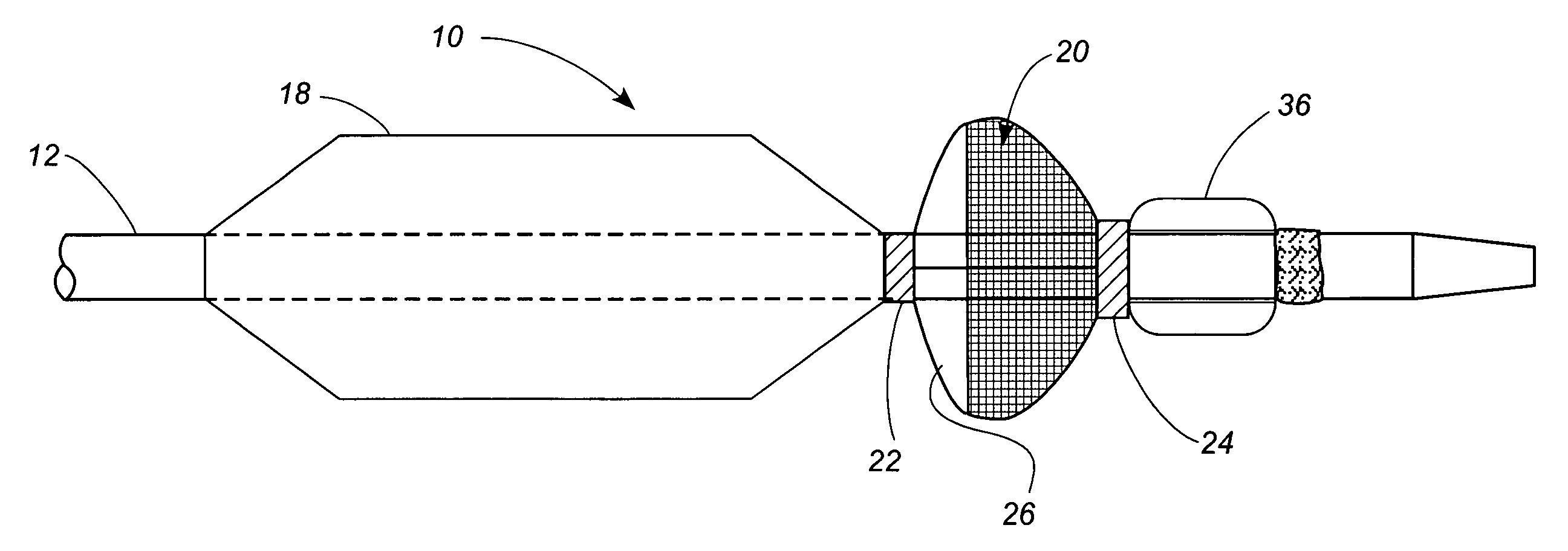
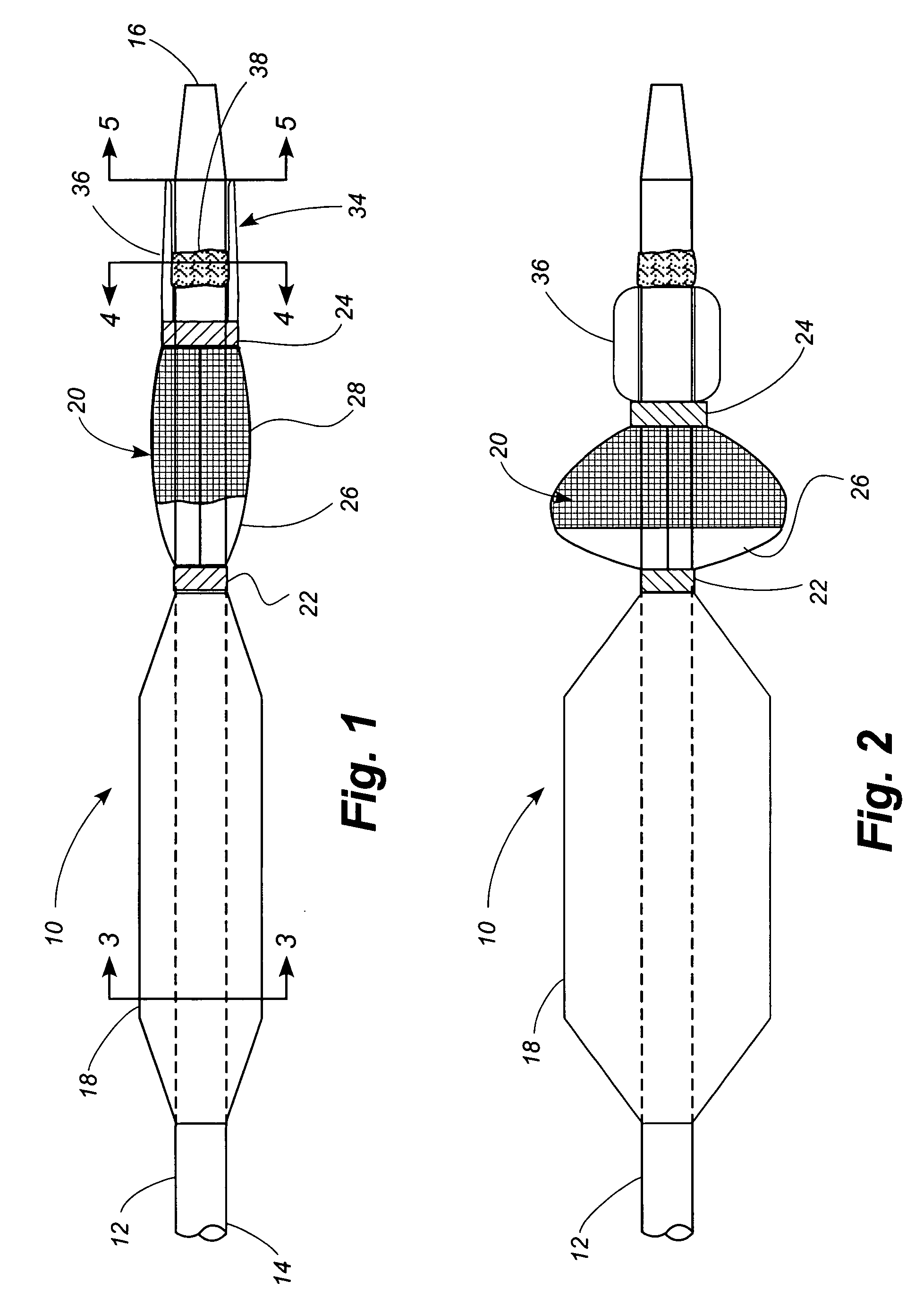
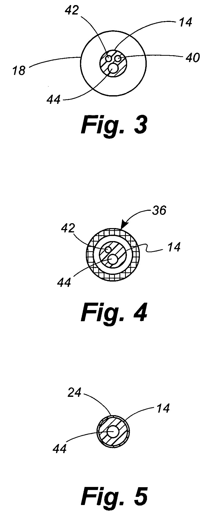
[0049] Referring now to the drawings, in which identical numbers indicate identical elements throughout the various views, FIGS. 1 and 2 illustrate a first embodiment of a percutaneous transluminal angioplasty device 10 according to the present invention. The device 10 comprises an elongated catheter 12 having a shaft 14 with a proximal end (not shown) and a distal end 16. Spaced a short distance proximally from the distal end 16 of the catheter 12 is an angioplasty balloon 18 of conventional design. In FIG. 1 the angioplasty balloon 18 is shown in a deflated or collapsed condition. In FIG. 2 the angioplasty balloon 18 is shown in an inflated condition.

[0050] Located between the angioplasty balloon 18 and the distal tip 14 of the catheter 12 is a collapsible filter 20. The filter 20 includes a proximal ring portion 22 and a distal ring portion 24. A plurality of elongated ribs 26 extend generally longitudinally between the proximal and distal rings 22, 24. These ribs can be made of...


PUM


Abstract

A percutaneous transluminal angioplasty device includes an embolic filter mounted to the catheter shaft at a location distal to the angioplasty balloon. Thus the filter is downstream from the blockage and is properly positioned to capture embolic particles that may be set loose into the blood stream as the angioplasty procedure is performed. The embolic filter is normally collapsed against the catheter shaft to facilitate introduction and withdrawal of the device to and from the operative site. Once the angioplasty balloon is properly positioned, however, means operatively associated with the embolic filter are actuated to erect the filter to position a filter mesh across the lumen of the vessel.

Description

CROSS-REFERENCE TO RELATED APPLICATION [0001] This application claims priority to Provisional Patent Application No. 60 / 560,934 filed Apr. 8, 2004.TECHNICAL FIELD [0002] The present invention relates generally to surgical devices and relates more specifically to a percutaneous transluminal angioplasty device. BACKGROUND OF THE INVENTION [0003] The vascular bed supplies a constant flow of oxygen-rich blood to the organs. If plaque builds up in these vessels, blockages can develop, reducing blood flow to the organs and causing adverse clinical symptoms, up to and including fatality. [0004] Angioplasty is a catheter-based procedure performed by a physician to open up a blocked vessel and restore blood flow. An entry site is opened, for example in the patient's groin, arm, or hand, and a guide wire and catheter are advanced under fluoroscopic guidance to the location of the blockage. A catheter having a small balloon adjacent its distal end is advanced under fluoroscopic guidance until ...

Claims


Application Information

Patent Timeline
Patent Type & Authority Applications(United States)
IPC IPC(8): A61F2/01A61F2/84A61M29/00A61M29/02
CPCA61F2230/0069A61F2230/008A61F2/013A61F2/958A61F2230/0008A61F2002/018A61F2230/0006A61F2/01A61M25/104
Inventor SACHAR, RAVISHSUTTON, GREGGROBERTS, LARRY A.
Owner CONTEGO MEDICAL
Why Eureka
Try Eureka