
System-level simulation of devices having diverse timing

a hardware simulation and timing technology, applied in the field of hardware simulation, can solve the problems of delay in software design and testing, time-consuming and expensive process of producing electronic devices, and inability to develop software, etc., and achieve the effect of increasing the speed and versatility of hardware simulation

Inactive Publication Date: 2005-10-13
CARBON DESING SYST
View PDF23 Cites 19 Cited by
  • Summary
  • Abstract
  • Description
  • Claims
  • Application Information

AI Technical Summary

Benefits of technology

[0007] The present invention increases the speed and versatility of hardware simulations. In general, the invention represents hardware components as executable objects that not only may be tested and run individually to simulate the behavior of a modeled hardware device, but which can be organized into a multi-object circuit modeling device behaviors and interactions among them. The various devices respect each other's timing requirements, so the simulation is cycle-accurate, but do not require the simulation to explicitly execute each clock cycle in order to maintain overall timing integrity. The devices may operate according to timing regimes that differ from the overall system timing.

Problems solved by technology

The process of producing electronic devices is time-consuming and expensive.
Due to the slow speed of many current simulators, it may be necessary to delay much of the design and testing of such software until after early versions of the actual hardware become available.
As a result, software development may not be possible until relatively late in the design cycle, potentially causing significant delays in bringing some electronic devices to market.
Reaching such simulation speeds, however, generally requires operating trade-offs.
For example, a high-speed simulation may not fully model the functionality of the hardware, perhaps abstracting components to the point of being accurate in terms of interface only.
As a result, such a simulation is limited in its reflection of how the system—software and hardware—will eventually run.
But again, due to the trade-off between capability and speed, such simulations generally run slowly and consequently limit the efficiency with which hardware and software may be co-designed.
One challenge attending the development of fast-operating simulations is the need to accommodate inconsistent timing requirements among devices, and to avoid device collisions.
Each simulated device may have its own timing, and its independent execution can interfere with proper execution of other devices.
Unfortunately, the price of this accuracy is slow execution due to the need to process every clock cycle, as well as design constraints—that is, it may be inappropriate, as a design matter, to make all devices “slaves” to a single environmental timing regime.

Method used


Image

  • System-level simulation of devices having diverse timing
  • System-level simulation of devices having diverse timing
  • System-level simulation of devices having diverse timing

Examples


Embodiment Construction

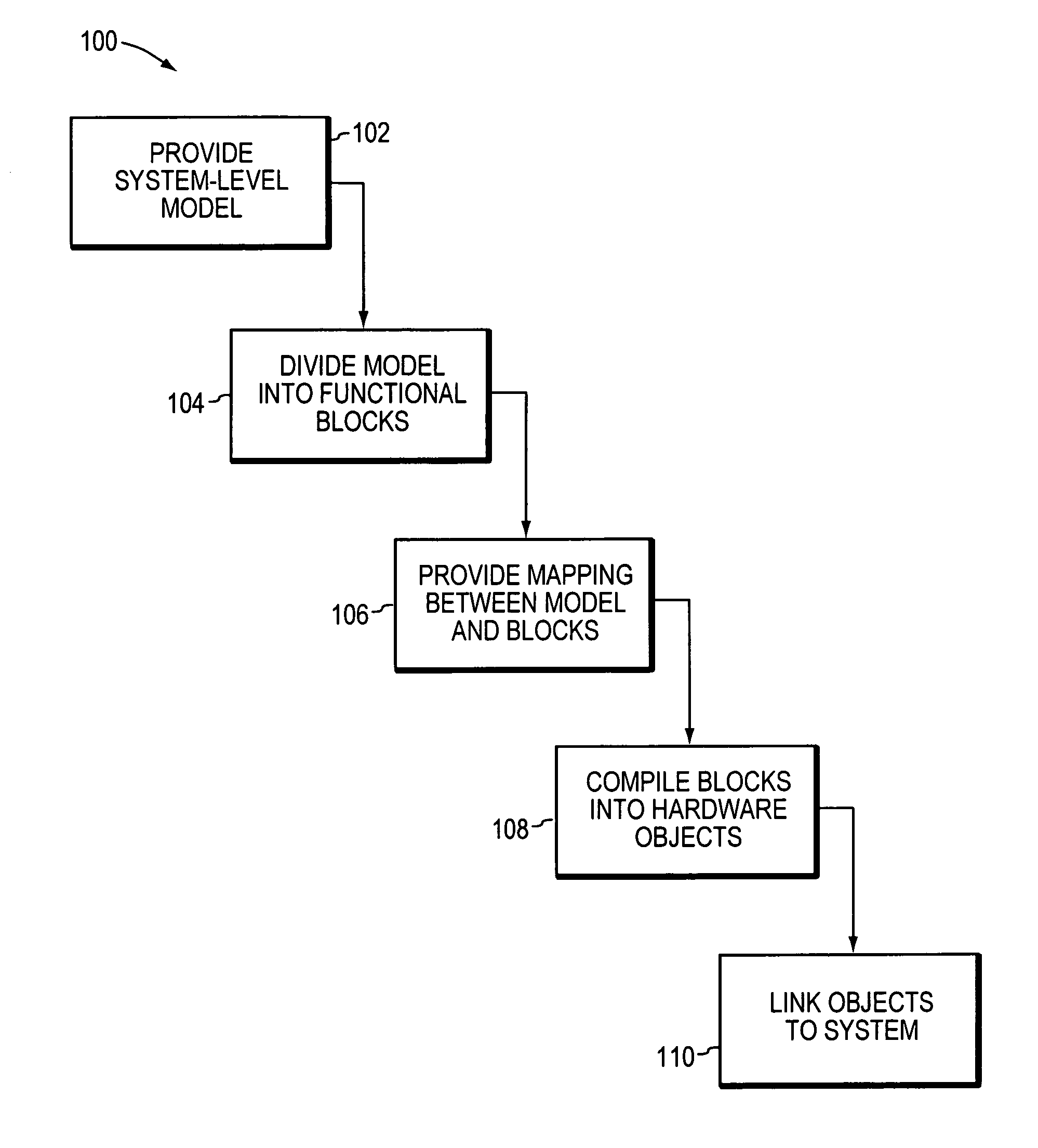
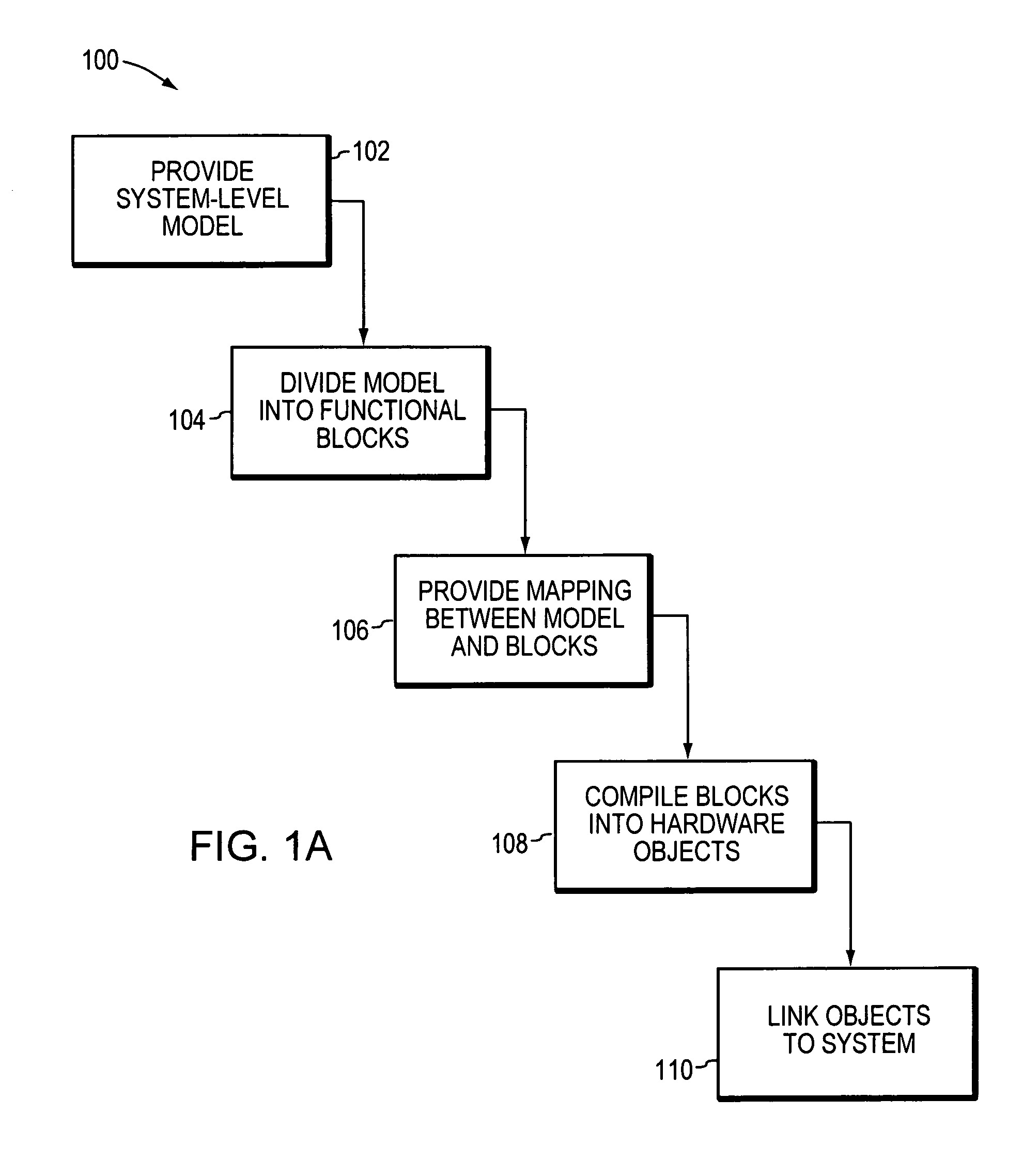
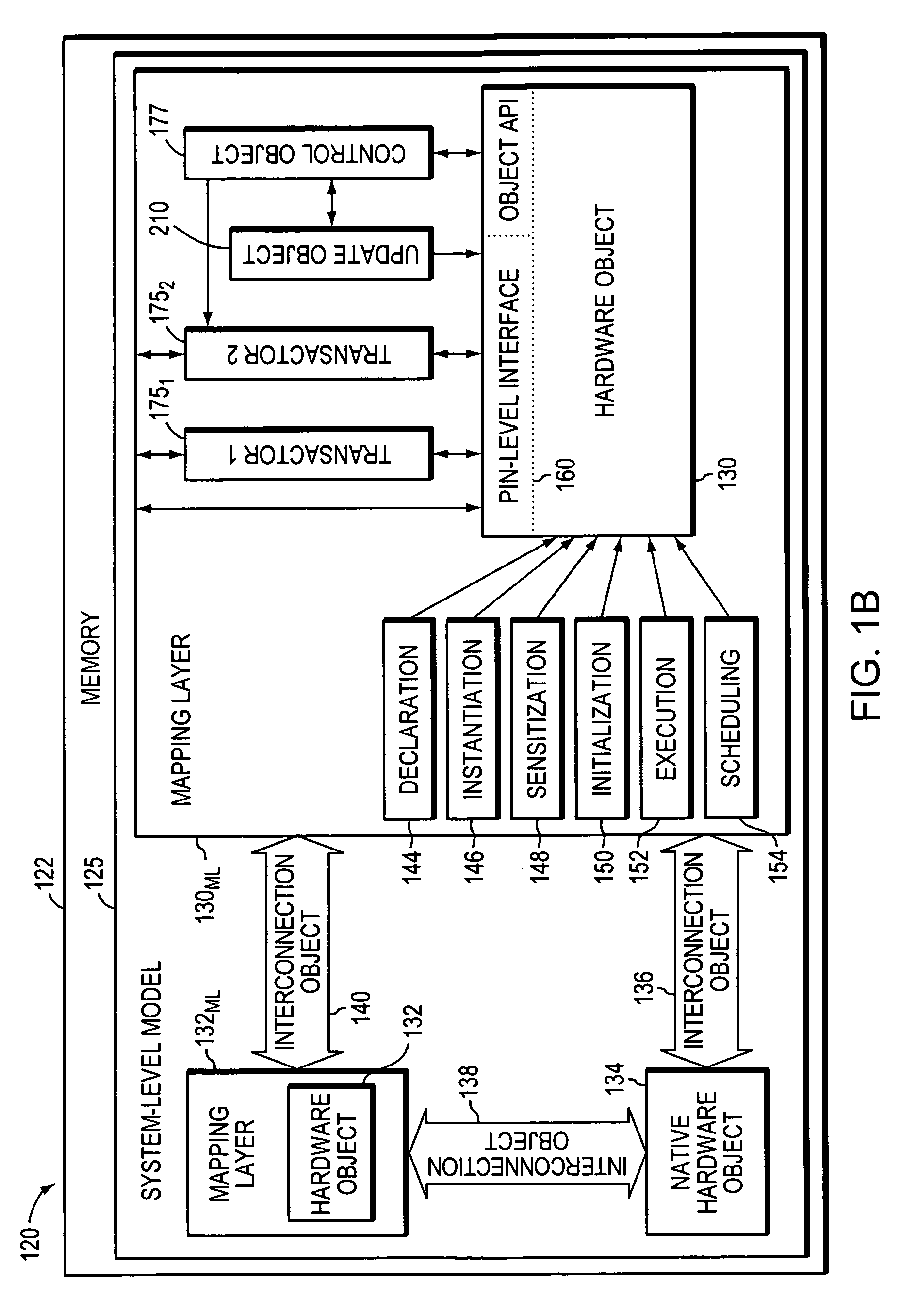
[0024] In brief overview, FIG. 1 is a flowchart depicting a method 100 in accordance with an embodiment of the invention for optimizing a system-level simulation of a hardware device to achieve a balanced simulation of low-level hardware specifics at high run-speeds. Broadly, the method provides a system-level model or execution environment (STEP 102), divides the model into functional blocks of high-level code (STEP 104), provides a mapping between the system-level model and the functional blocks (STEP 106), and compiles the functional blocks into API-accessible, run-time object code (STEP 108). For example, if the source code (i.e., functional block) of a FIFO buffer was written in C and stored in a file named fifo.c, the compiled run-time object code may reside in a file named fifo.o (hardware object). Pre-compiled objects in some embodiments are recompiled. Following compilation (STEP 108), the run-time hardware objects are linked (STEP 110) to the system-level model. The linkin...


PUM


Abstract

A system-level simulation of hardware devices, each of which may have different timing requirements, utilizes one or more master objects and update objects (e.g., a clock object) in order to coordinate the device simulations. The master object may, for example, advance the update objects according to one or more criteria and then instruct an object representing a hardware device to execute.

Description

FIELD OF THE INVENTION [0001] The present invention relates generally to hardware simulation and, more specifically, to high-speed, object-oriented hardware simulations. BACKGROUND OF THE INVENTION [0002] Electronic hardware design is typically performed using register transfer level (RTL) descriptions of the device being designed. Hardware description languages such as Verilog allow hardware designers to describe the electronic devices that they are designing, and to have those descriptions synthesized into a form that can be fabricated. [0003] The process of producing electronic devices is time-consuming and expensive. As a result, various simulation systems have been developed to permit hardware designs to be verified prior to actually producing an electronic device. Typically, a description of an electronic device is exercised using a simulator. The simulator generally includes a simulation kernel that runs the simulation either in software, or using simulation hardware, which t...

Claims


Application Information

Patent Timeline
Patent Type & Authority Applications(United States)
IPC IPC(8): G06F17/50
CPCG06F17/5022G06F30/33
Inventor BELLANTONI, MATTHEWNEIFERT, WILLIAMLADD, ANDREWGRASSE, MATTHEWKOSTICK, MARK
Owner CARBON DESING SYST
Learn More