
Method and apparatus for selective, incremental, reconfigurable and reusable semiconductor manufacturing resolution-enhancements

a semiconductor and manufacturing technology, applied in the direction of instruments, computing, electric digital data processing, etc., can solve the problems of inability to apply incrementally or selectively reconfigurable ret/opc, difficult verification of enhancement results, and inability to ensure the accuracy of the improvement, so as to improve the manufacturability and yield

Inactive Publication Date: 2005-10-13
RPX CORP
View PDF5 Cites 225 Cited by
  • Summary
  • Abstract
  • Description
  • Claims
  • Application Information

AI Technical Summary

Benefits of technology

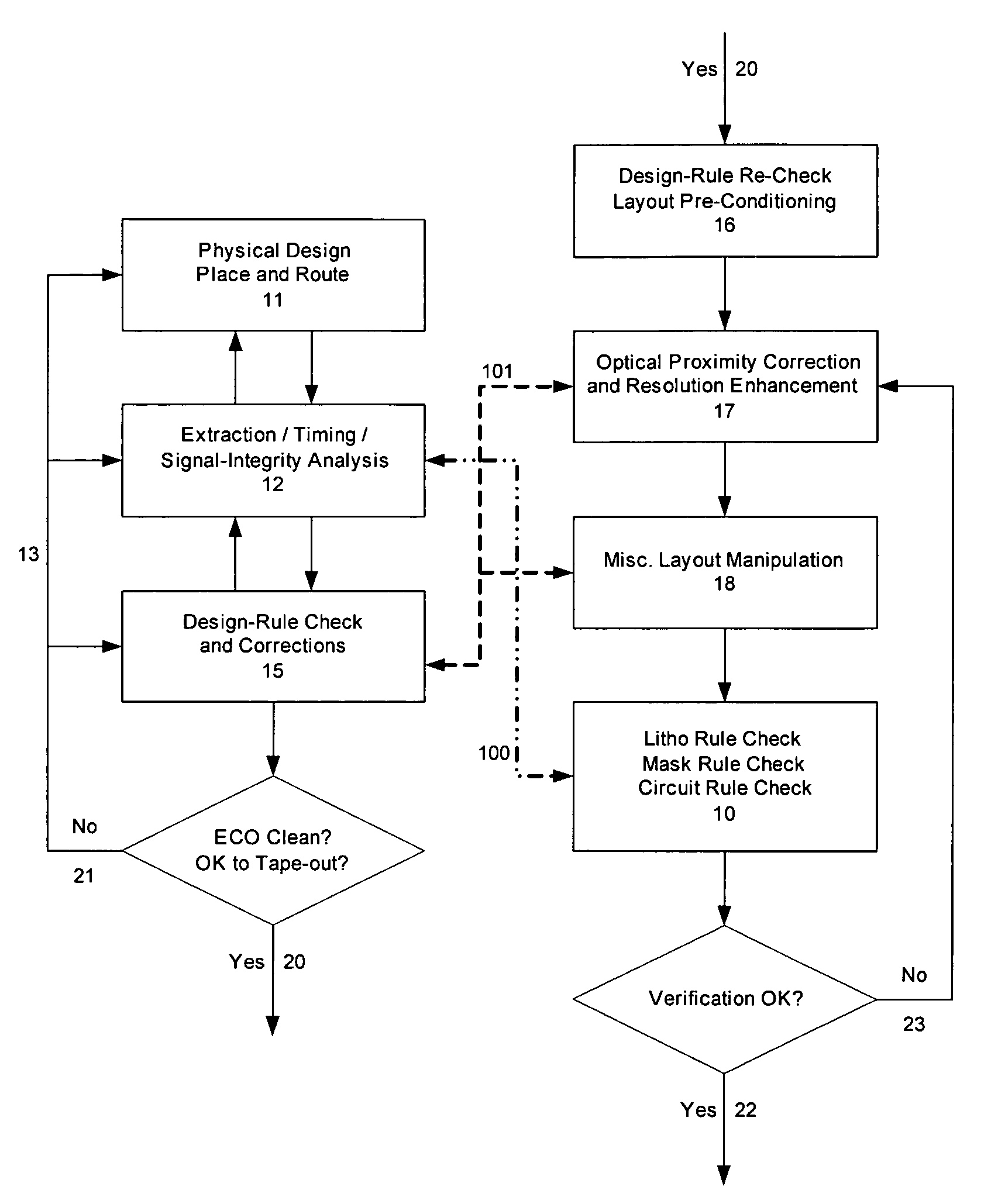
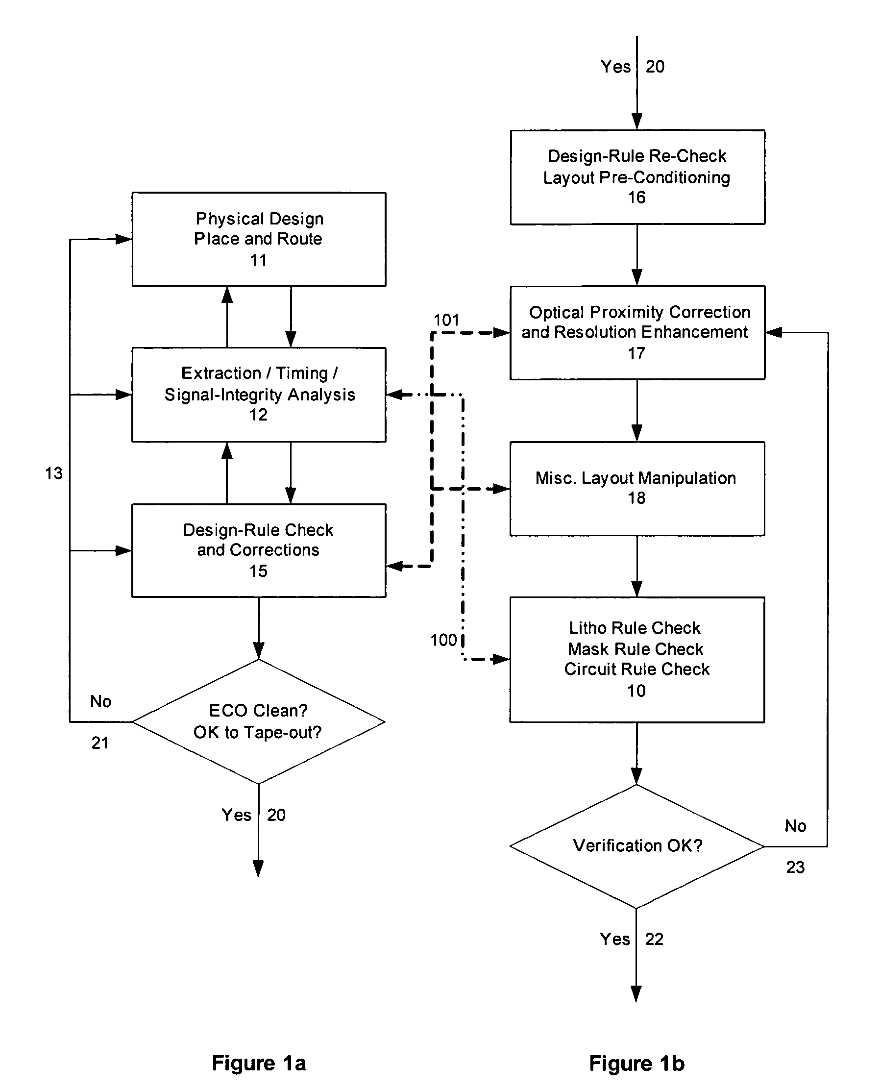
[0006] An automated system for incremental and selective application and reconfiguration of resolution-enhancements, such as optical proximity corrections (OPC), on integrated circuit (IC) layouts in order to provide enhancement, enhancement fix, reconfiguration and layout reuse capability. Starting from original layouts and one or more associated resolution-enhanced layouts, intermediate resolution-enhancement state layouts are reconstructed. Using a damping algorithm, selective localized resolution-enhancement reconfigurations, modifications, and / or perturbations are introduced on any existing layout enhancements in order to improve manufacturability and yield.

Problems solved by technology

While conventional resolution-enhancement technologies (RET), such as optical proximity correction (OPC), are widely applied in advanced design-to-manufacturing processes in order to improve manufacturability and yield of circuit layouts, such enhancements are difficult to verify and verification results do not necessarily translate to systematic methods of correcting RET / OPC.
Furthermore, RET / OPC cannot be applied incrementally or reconfigured selectively, due to proximity and hierarchical interactions of the enhancements.
This approach is inefficient and time-consuming.
The conventional approach presents a further disadvantage in that it prohibits the application of RET / OPC to standard cells and intellectual property (IP) cores in a way that allows such layouts to be reused as well as characterized early in the design flow.

Method used


Image

  • Method and apparatus for selective, incremental, reconfigurable and reusable semiconductor manufacturing resolution-enhancements
  • Method and apparatus for selective, incremental, reconfigurable and reusable semiconductor manufacturing resolution-enhancements
  • Method and apparatus for selective, incremental, reconfigurable and reusable semiconductor manufacturing resolution-enhancements

Examples


Embodiment Construction

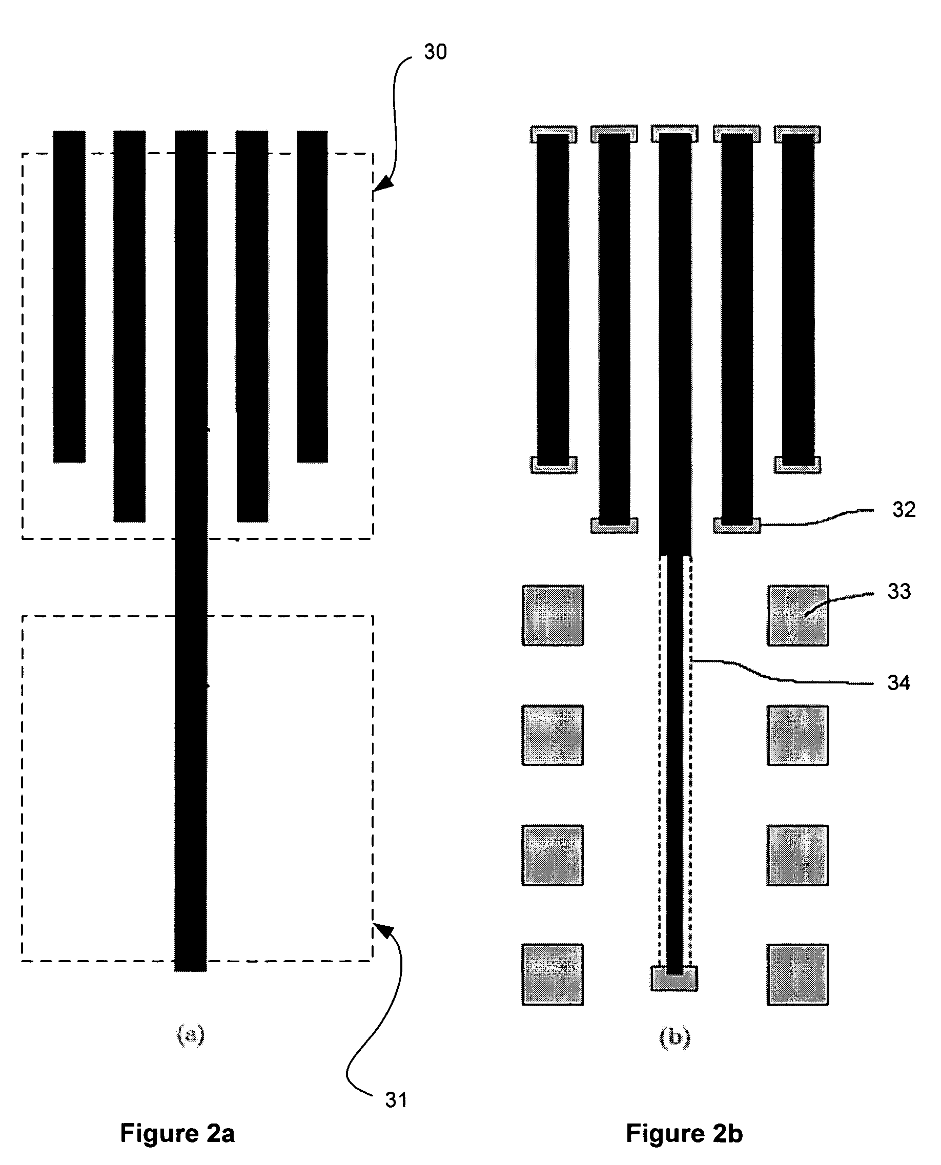
[0019] The following serves as a glossary of terms as used herein: [0020] Optical Proximity Correction (OPC)—Corrections applied to integrated circuit layout to pre-compensate proximity effects (i.e. on-silicon layout dimension / shape distortions caused by neighboring layout patterns within a certain proximity) introduced mainly by optical lithography in the manufacturing process. [0021] Scattering-Bar (also known as Assist-Feature)—Correction features placed next to isolated edges on a mask in order to adjust the edge intensity at the isolated edge to match the edge intensity at a densely packed edge and thereby cause the feature having at least one isolated edge to have nearly the same width as features having densely packed edges. [0022] Alternative Phase-Shifting—A technique for improving lithography resolution, phase-shifting shifts the phase of a first region of incident light waves approximately 180 degrees relative to a second, adjacent region of incident light waves. In this...


PUM


Abstract

An automated design for manufacturability platform for integrated physical verification and manufacturing enhancement operations. Given original layouts and one or more associated resolution-enhanced layouts, intermediate resolution-enhancement state layouts are reconstructed, and selective localized resolution-enhancement reconfigurations, modifications, and / or perturbations are introduced on any existing enhancements in order to improve manufacturability and yield.

Description

BACKGROUND [0001] 1. Field [0002] The present invention relates to design, verification and manufacturing of integrated circuits, and in particular to the incremental and selective reconfiguration of resolution-enhancements on integrated circuit layouts. [0003] 2. Related Art [0004] While conventional resolution-enhancement technologies (RET), such as optical proximity correction (OPC), are widely applied in advanced design-to-manufacturing processes in order to improve manufacturability and yield of circuit layouts, such enhancements are difficult to verify and verification results do not necessarily translate to systematic methods of correcting RET / OPC. Furthermore, RET / OPC cannot be applied incrementally or reconfigured selectively, due to proximity and hierarchical interactions of the enhancements. The result is the application of “one-shot” RET / OPC operations to an entire circuit layout, followed by a verification step, wherein a negative result of the verification step forces ...

Claims


Application Information

Patent Timeline
Patent Type & Authority Applications(United States)
IPC IPC(8): G06F17/50
CPCG06F17/5068G06F30/39
Inventor WU, SHAO-POWANG, XINTANG, HONGBOHUNG, MEG
Owner RPX CORP
Learn More