
Optimized system-level simulation

a system-level simulation and optimization technology, applied in the field of hardware simulation, can solve the problems of delay in software design and testing, time-consuming and expensive process of producing electronic devices, and inability to realize software development, so as to facilitate intercommunication and increase the speed and versatility of hardware simulations.

Inactive Publication Date: 2005-10-13
CARBON DESING SYST
View PDF25 Cites 17 Cited by
  • Summary
  • Abstract
  • Description
  • Claims
  • Application Information

AI Technical Summary

Benefits of technology

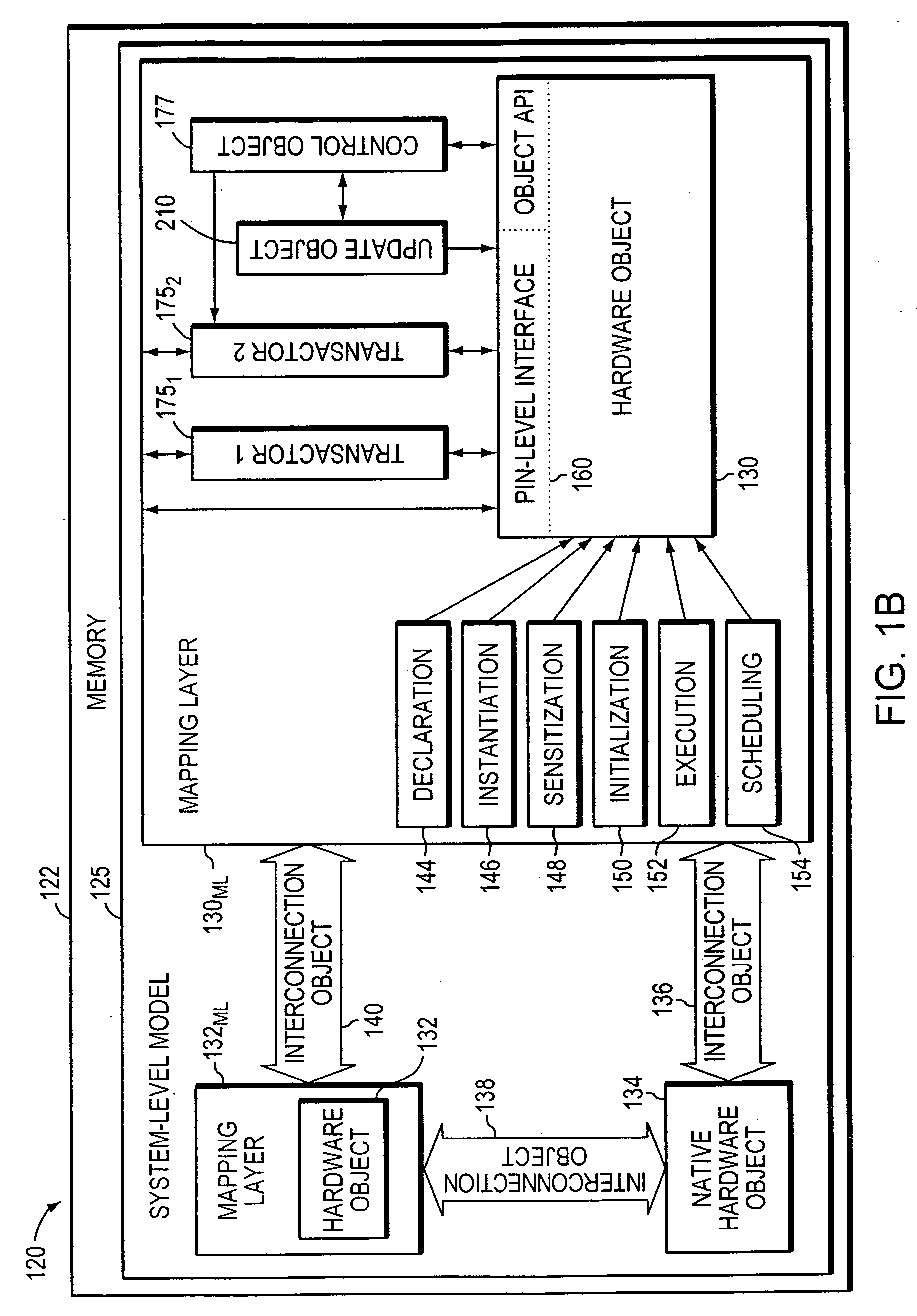
[0007] The present invention to increase the speed and versatility of hardware simulations by representing hardware components as executable objects that not only may be tested and run individually to simulate the behavior of a modeled hardware device, but which can be organized into a multi-object circuit modeling device behaviors and interactions among them. Using the invention, a designer may define objects to model the behavior of hypothetical or actual devices, and then define their interconnections and interactions. The invention allows objects to be integrated into diverse system-level environments, and also accommodates different types of objects. For example, objects may be re-used from different simulations or generated from templates, and the invention facilitates their intercommunication even if they are not configured for “native” communication within a new system-level environment.
[0008] In accordance with the invention, integration of objects within their environment (and, as a result, among themselves) may be accomplished by mapping between the objects and the environment at a functional level rather than the detailed interface level. This “abstract” mapping avoids clashes between, e.g., object and environment-level interfaces that have different timing requirements or operate at different levels of abstraction. A hardware object, for example, may “expect” to be called at every clock edge while the system-level environment operates at a higher level of abstraction, e.g., presenting data transactions only when data needs to be transferred into or out of the hardware object. Moreover, different types of transactions may themselves have different timing and data requirements.
[0011] Mapping may involve API mapping and / or abstraction mapping. API mapping involves receiving input data from the system-level model, translating the input data into a format readable by hardware object, providing the input data to the hardware object, and translating output data from the hardware object into a format readable by the system-level model. In other words, API mapping may be limited to simple translation functions. For example, the system-level model may comprise an API presenting an interface accurate with respect to boundaries of a system clock but having system-specific data and access requirements, while hardware objects comprise APIs presenting an interface accurate with respect to boundaries of the system clock but having object-specific data and access requirements. API mapping reconciles the requirements of the system-level API and each object-level API so as to facilitate data interchange therebetween while maintaining adherence to the system clock.

Problems solved by technology

The process of producing electronic devices is time-consuming and expensive.
Due to the slow speed of many current simulators, it may be necessary to delay much of the design and testing of such software until after early versions of the actual hardware become available.
As a result, software development may not be possible until relatively late in the design cycle, potentially causing significant delays in bringing some electronic devices to market.
Reaching such simulation speeds, however, generally requires operating trade-offs.
For example, a high-speed simulation may not fully model the functionality of the hardware, perhaps abstracting components to the point of being accurate in terms of interface only.
As a result, such a simulation is limited in its reflection of how the system—software and hardware—will eventually run.
But again, due to the trade-off between capability and speed, such simulations generally run slowly and consequently limit the efficiency with which hardware and software may be co-designed.

Method used


Image

  • Optimized system-level simulation
  • Optimized system-level simulation
  • Optimized system-level simulation

Examples


Embodiment Construction

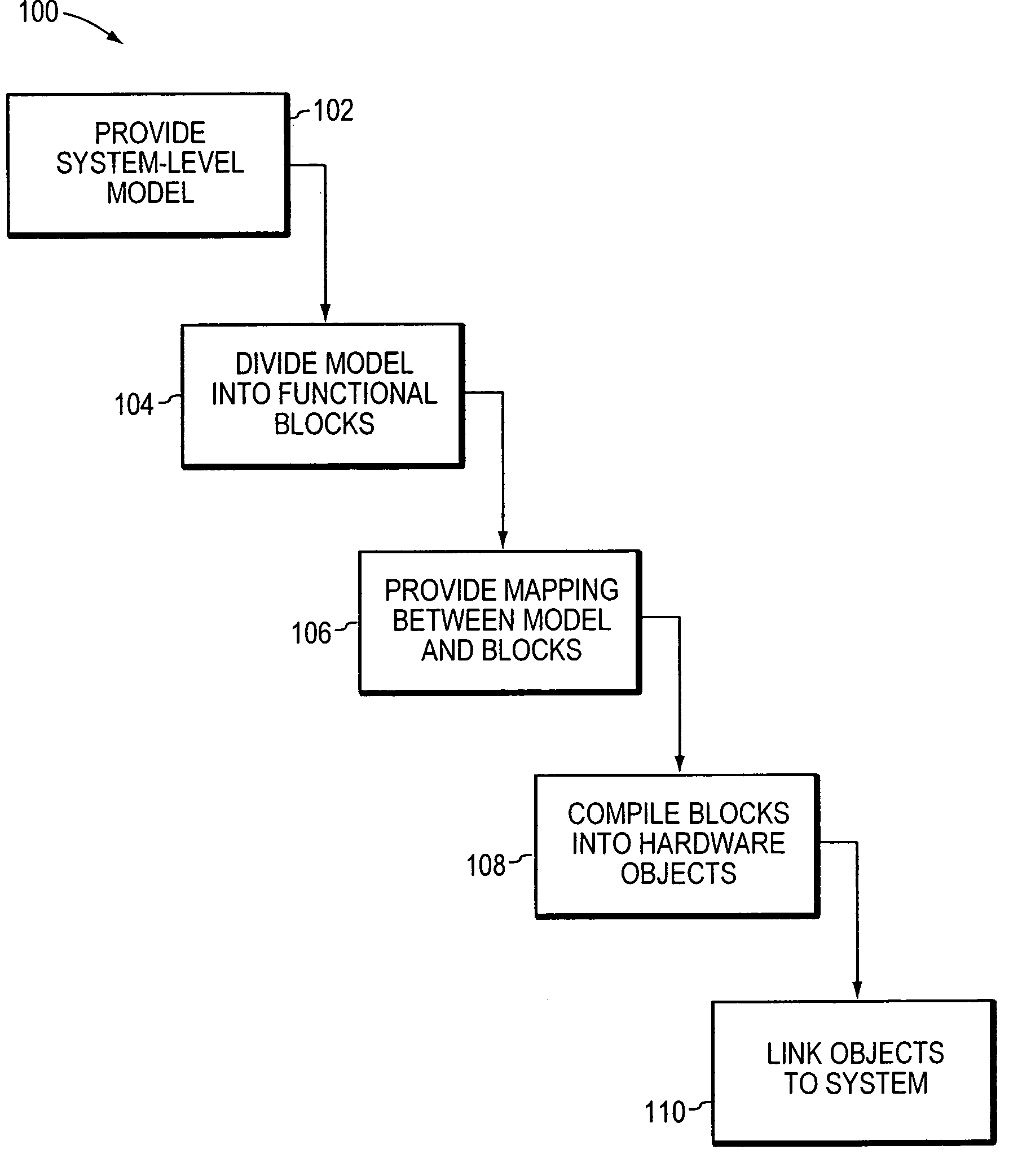
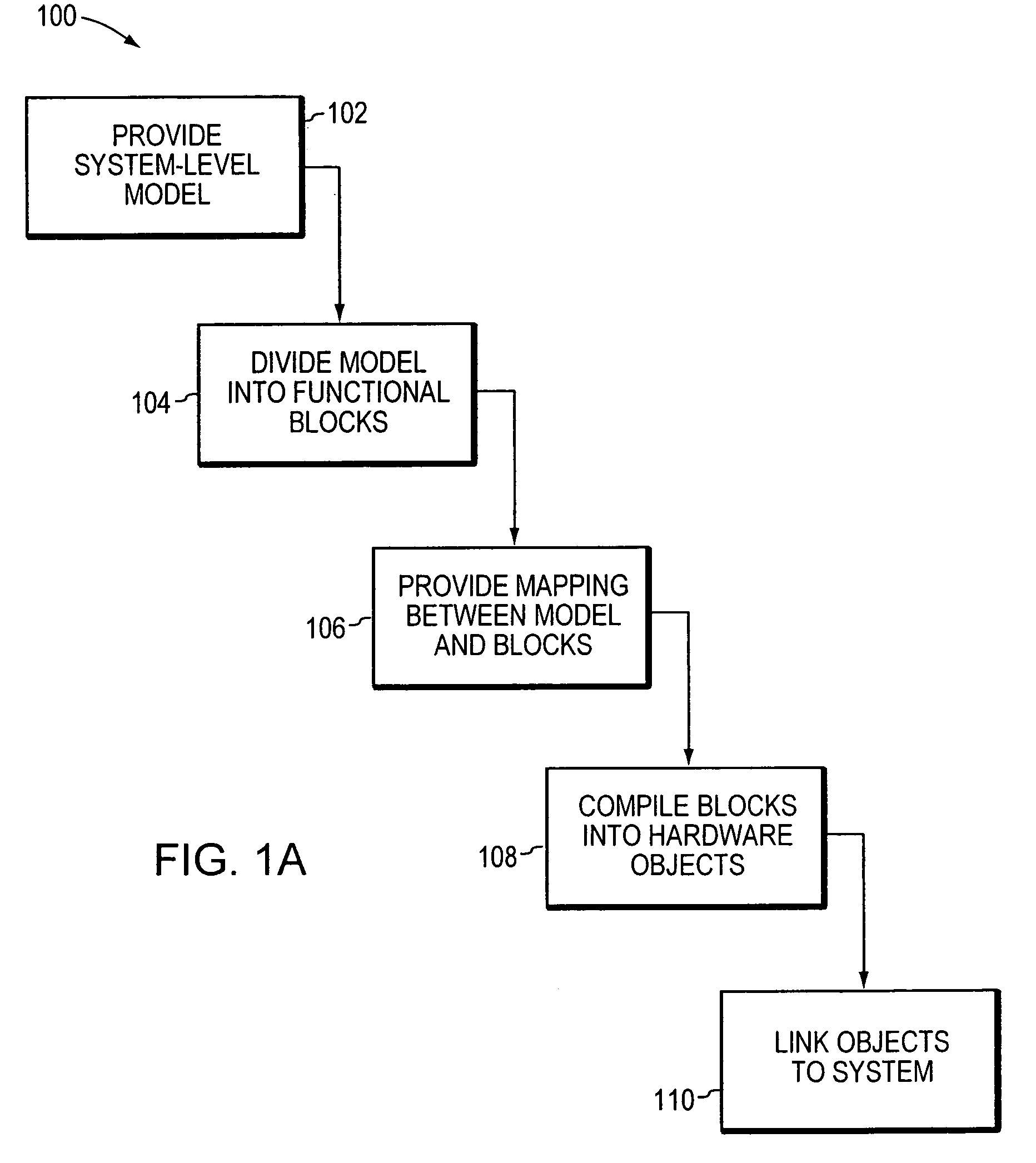
[0025] In brief overview, FIG. 1 is a flowchart depicting a method 100 in accordance with an embodiment of the invention for optimizing a system-level simulation of a hardware device to achieve a balanced simulation of low-level hardware specifics at high run-speeds. Broadly, the method provides a system-level model or execution environment (STEP 102), divides the model into functional blocks of high-level code (STEP 104), provides a mapping between the system-level model and the functional blocks (STEP 106), and compiles the functional blocks into API-accessible, run-time object code (STEP 108). For example, if the source code (i.e., functional block) of a FIFO buffer was written in C and stored in a file named fifo.c, the compiled run-time object code may reside in a file named fifo.o (hardware object). Pre-compiled objects in some embodiments are recompiled. Following compilation (STEP 108), the run-time hardware objects are linked (STEP 110) to the system-level model. The linkin...


PUM


Abstract

Integration of a system-level simulation with one or more hardware device simulations is accomplished using a mapping layer, which allows the system-level simulation to interact with the hardware device simulation at a pin level, an object level, and an abstract level. The overall simulation may operate with respect to a clock or timing device or it may operate with respect to transactions.

Description

FIELD OF THE INVENTION [0001] The present invention relates generally to hardware simulation and, more specifically, to high-speed, object-oriented hardware simulations. BACKGROUND OF THE INVENTION [0002] Electronic hardware design is typically performed using register transfer level (RTL) descriptions of the device being designed. Hardware description languages such as Verilog allow hardware designers to describe the electronic devices that they are designing, and to have those descriptions synthesized into a form that can be fabricated. [0003] The process of producing electronic devices is time-consuming and expensive. As a result, various simulation systems have been developed to permit hardware designs to be verified prior to actually producing an electronic device. Typically, a description of an electronic device is exercised using a simulator. The simulator generally includes a simulation kernel that runs the simulation either in software, or using simulation hardware, which t...

Claims


Application Information

Patent Timeline
IPC IPC(8): G06F9/44G06F17/50
CPCG06F2217/86G06F17/5022G06F30/33G06F2117/08
Inventor BELLANTONI, MATTHEWNEIFERT, WILLIAMLADD, ANDREWGRASSE, MATTHEWKOSTICK, MARK
Owner CARBON DESING SYST
Learn More