Combustion-type power tool

a power tool and combustion type technology, applied in the direction of stapling tools, nailing tools, explosive based starters, etc., can solve the problems of motor property degradation, motors manufactured based on special specifications, and high cost, and achieve the effect of less damage and easy manufacturing

Active Publication Date: 2005-10-20
HITACHI KOKI CO LTD
View PDF12 Cites 11 Cited by
  • Summary
  • Abstract
  • Description
  • Claims
  • Application Information

AI Technical Summary

Benefits of technology

[0015] It is therefore an object of the present invention to dissolve the above-described problems accompanying the conventiona...

Problems solved by technology

The motor may be damaged by the impact repeatedly applied to the motor, resulting in degradation of the property of the motor.
Therefore, general-purpose motors cannot be employed but motors manufactured based on a special specification, which are expensive in cost, are required.
Due to the different materials forming the integrated buffer member...

Method used


Image

  • Combustion-type power tool
  • Combustion-type power tool
  • Combustion-type power tool

Examples


second embodiment

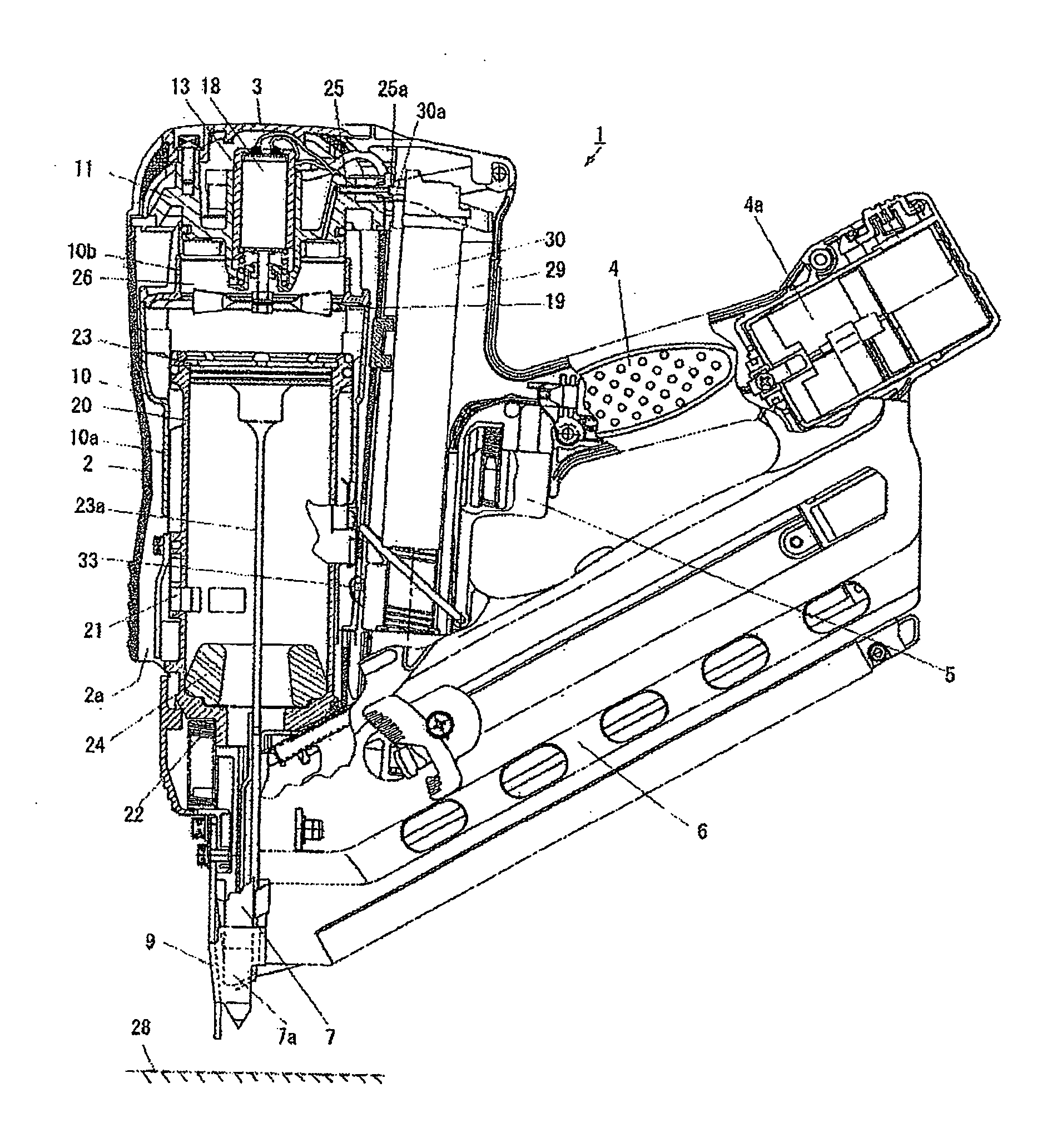
[0064] A motor holder employed in the combustion-type nail driver will be described while referring to FIG. 8. FIG. 8 is a vertical cross-sectional view showing the motor holder 13 and its associated components. A motor 18 is accommodated in the motor holder 13 formed from a material of a low friction factor such as plastic. The motor holder 13 is a hollow cylindrical member adapted to receive the motor 18. The motor 18 is supported by the motor holder 13 and the upper side of the motor 18 is fixed by hooks 13b provided above the motor holder 13. Three protrusions 13c protrude radially outwardly from the intermediate portion of the motor holder 13. The protrusions 13c are formed at the time of mold shaping the motor holder 13. The protrusions 13c perform up and down movements while contacting the inner wall of the motor holder receiving portion 11a formed in the cylinder head 11 when impact is imparted upon the motor 18. Friction between the protrusions 13c and the motor holder rec...

fifth embodiment

[0068] A combustion-type nail driver will be described while referring to FIGS. 11 through 14. The nail driver shown in FIGS. 11 through 14 is basically the same in structure as that shown in FIGS. 3 through 7 but differs therefrom in the material and shape of the motor holder 13.

[0069] The motor holder 13 according to the fifth embodiment is formed from a metal such as aluminum. The metallic motor holder 13 is imposed on a role of dissipating combustion heat generated at the time firing the nails and also heat generated from the motor 18. As shown in FIG. 13, the motor 18 is inserted from the upper end of the motor holder 13 and held therein with a pin 49 so as not to be detached therefrom. One end of the coil spring 15 is inserted into and held by the groove 13a formed in the bottom of the motor holder 13. Another end of the coil spring 15 is inserted into the groove 11b engraved in the motor holder receiving portion 11a and is fixed thereto by a screw 32.

[0070]FIG. 11 shows an ...


PUM


Abstract

A combustion-type nail driver uses a motor for driving a fan. A motor holder formed from plastic accommodates the motor. A cylinder head has a motor holder receiving portion in which the motor holder is slidably movably disposed. A coil spring has one end secured to the motor holder and another end secured to the cylinder head to thereby support the motor holder. Initial acceleration applied to the motor when combustion occurs can be suppressed and impact imparted upon the motor can also be suppressed by friction between the outer periphery of the motor holder and the inner periphery of the motor holder receiving portion. A heat shielding plate is interposed between the lower end surface of the motor and the cylinder head in order to prevent hot air combustion gas from entering into the motor.

Description

BACKGROUND OF THE INVENTION [0001] 1. Field of the Invention [0002] The present invention relates generally to a combustion-type power tool, such as combustion-type nail driver for striking fastening members such as nails or studs into a workpiece wherein acceleration applied to a motor when combustion explosion occurs or a piston impinges upon a bumper is suppressed. [0003] 2. Description of the Related Art [0004] A combustion-type nail driver ignites air-fuel mixed gas confined in a combustion chamber and translates voluminal expansion of the gas into power. A fan is disposed within the combustion chamber to stir air and fuel to enhance the combustion property of the mixed gas. [0005] The fan is rotated by a motor. The fan generates turbulence of the mixed gas in the combustion chamber and promotes combustion of the gas. Occurrence of explosive combustion in the combustion chamber brings the voluminal expansion of the gas and generates impact. The impact thus generated is transmit...

Claims


Application Information

Patent Timeline
IPC IPC(8): B25C1/08
CPCB25C1/08
Inventor AKIBA, YOSHITAKANISHIKAWA, TOMOMASAYAMAMOTO, KUNIOOHTSU, SHINKIFUJISAWA, HARUHISA
Owner HITACHI KOKI CO LTD
Why Eureka
Try Eureka