Capillary condenser/evaporator

a condenser and evaporator technology, applied in indirect heat exchangers, lighting and heating apparatus, etc., can solve the problems of limiting the heat transport capacity of heat pipes, affecting reducing the performance of wicks, so as to reduce the cross-sectional area

Active Publication Date: 2005-10-20
MIKROS MFG
View PDF24 Cites 84 Cited by
  • Summary
  • Abstract
  • Description
  • Claims
  • Application Information

AI Technical Summary

Benefits of technology

[0015] In another embodiment, the heat transfer device includes a capillary wick disposed between a first bridge and a second bridge. The first bridge may confront a first face of the capillary wick and may include a plurality of first internal passageways each having a first cross-sectional area. In this embodiment, the plurality of first internal passageways become less numerous in a direction away from the capillary wick and the cross-sectional areas of the plurality of first internal passageways become larger in a direction away from the capillary wick. A second bridge may confront a second face of the capillary wick, and may also include a plurality of second internal passageways each having a second cross-sectional area, wherein the plurality of second internal passageways become less numerous in a direction away from the capillary wick and the cross-sectional areas of the plurality of second internal passageways become larger in a direction away from the capillary wick.
[0016] In another embodiment, the heat transfer device includes a capillary structure, a heat interface, and a liquid-vapor manifold that transports both liquid and vapor. The liquid-vapor manifold may include one or more layers, each layer including one or more conduits and wherei

Problems solved by technology

This creates a large pressure drop for the liquid that effectively limits the maximum liquid flow rate, thereby limiting the heat transport capacity of the heat pipe.
Increasing the thickness of the wick translates into a higher thermal resistance at the evaporator portion and, perhaps more limiting, an increase in the liquid superheat at the interface between the inner surface of the tube and the wick.
Eventually, the superheat at the base of the wick becomes too large and boiling takes place in the wick, leading to a drying out of the wick.
When the wick dries out, the performance of the wi

Method used


Image

  • Capillary condenser/evaporator
  • Capillary condenser/evaporator
  • Capillary condenser/evaporator

Examples


Embodiment Construction

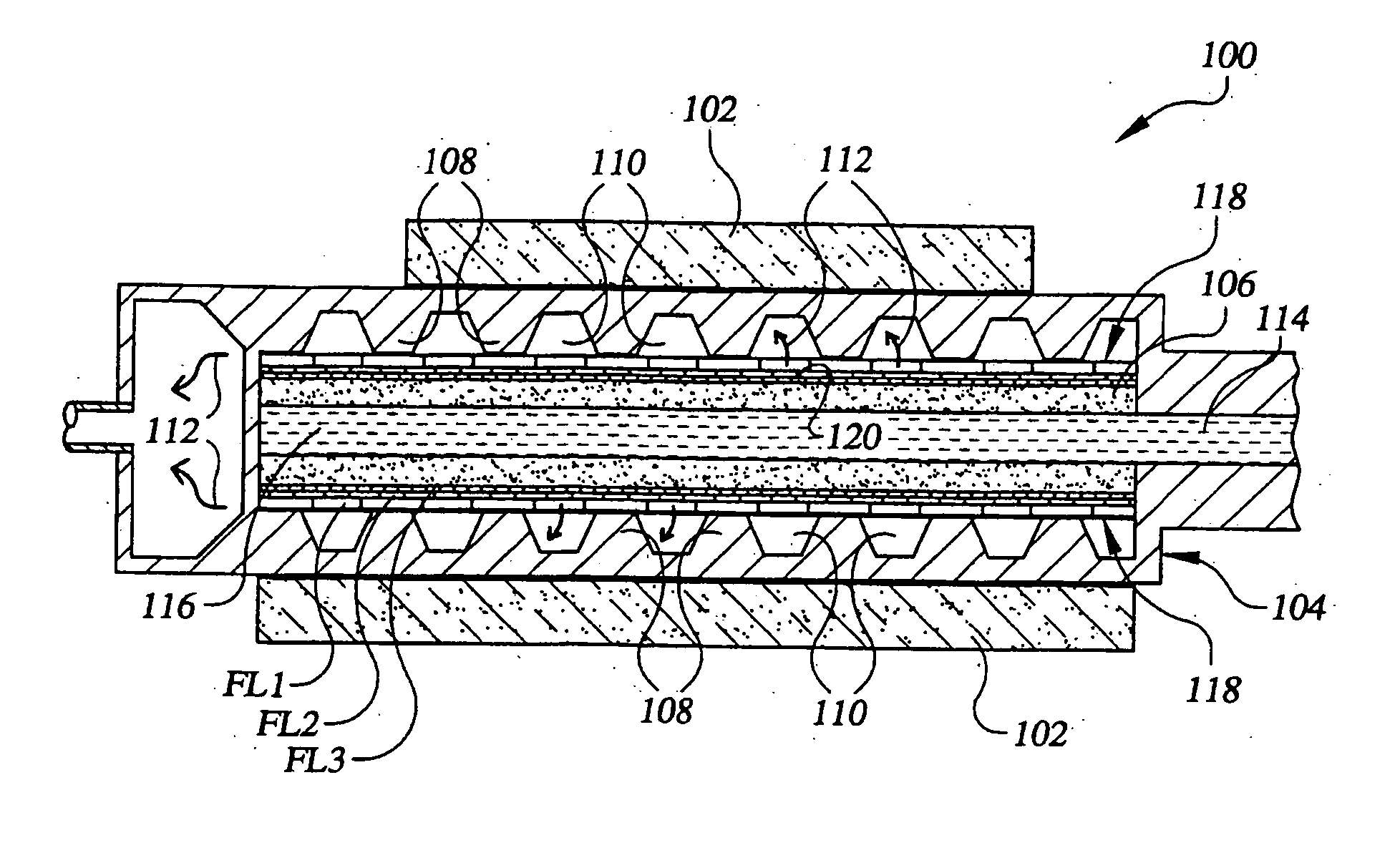
[0037] Referring now to the drawings, FIG. 2 illustrates a capillary heat exchanger which may be configured as an evaporator or condenser and which is identified generally by the numeral 100. For purposes of explanation, the following description will be in terms of a capillary evaporator, with the understanding that the description would also be applicable to a condenser. Like evaporator 20 discussed in the background section, above, capillary evaporator 100 may be incorporated into a two-phase heat-transfer system, such as the loop heat pipe (LHP) and capillary pumped loop (CPL) systems mentioned above, among others. Capillary evaporator 100 may be any size and / or shape suitable for interfacing with any of a variety of heat sources, such as heat source 102, that is desired to be cooled. Those skilled in the art will appreciate the variety of shapes and / or sizes of capillary evaporator 100 that may be made in accordance with the present invention and that the various capillary evap...


PUM


Abstract

A heat transfer device is disclosed for transferring heat to or from a fluid that is undergoing a phase change. The heat transfer device includes a liquid-vapor manifold in fluid communication with a capillary structure thermally connected to a heat transfer interface, all of which are disposed in a housing to contain the vapor. The liquid-vapor manifold transports liquid in a first direction and conducts vapor in a second, opposite direction. The manifold provides a distributed supply of fluid (vapor or liquid) over the surface of the capillary structure. In one embodiment, the manifold has a fractal structure including one or more layers, each layer having one or more conduits for transporting liquid and one or more openings for conducting vapor. Adjacent layers have an increasing number of openings with decreasing area, and an increasing number of conduits with decreasing cross-sectional area, moving in a direction toward the capillary structure.

Description

CROSS REFERENCES TO RELATED APPLICATIONS [0001] This application is a continuation-in-part of U.S. application Ser. No. 10 / 374,933, filed Feb. 26, 2003, entitled “Capillary Evaporator,” which claims priority to U.S. Provisional Patent Application No. 60 / 359,673, filed Feb. 26, 2002 and entitled “Fractal Capillary Evaporator.” The entire contents of the above applications are incorporated herein by reference in entirety.BACKGROUND OF THE INVENTION [0002] The present invention relates generally to the field of thermal management systems. More particularly, the present invention is directed to a heat transfer device for transferring heat to or from a fluid that is undergoing a phase change. [0003] Capillary condensers and evaporators are used in a variety of two-phase thermal management systems. As will be appreciated, many devices may be used as either an evaporator or a condenser, the difference between the two being primarily the direction of flow for the heat, liquid and / or vapor, ...

Claims


Application Information

Patent Timeline
IPC IPC(8): F28D15/02
CPCF28D15/043F28D15/0233
Inventor VALENZUELA, JAVIER A.
Owner MIKROS MFG
Why Eureka
Try Eureka