

Fabrication and integration of polymeric bioMEMS
- Summary
- Abstract
- Description
- Claims
- Application Information
AI Technical Summary
Benefits of technology
Problems solved by technology
Method used
Image

Examples
first embodiment
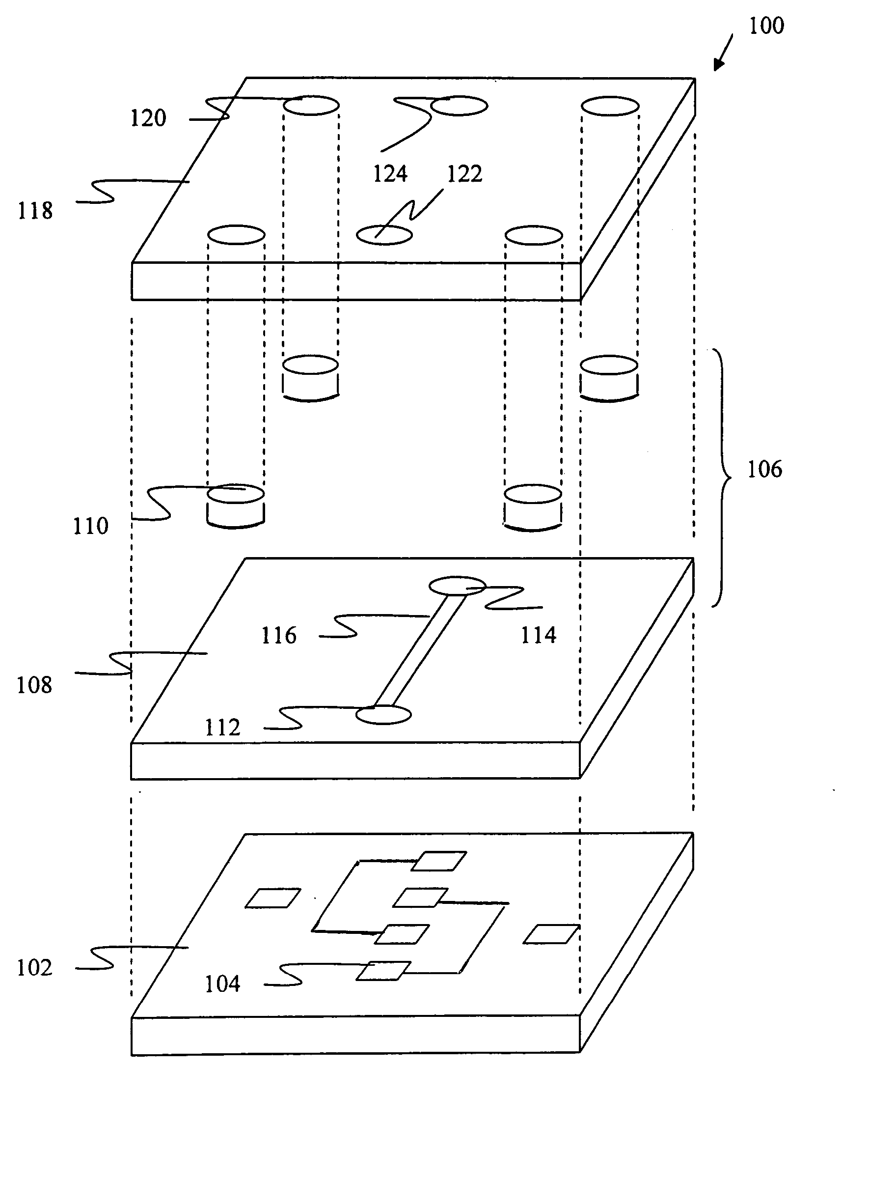
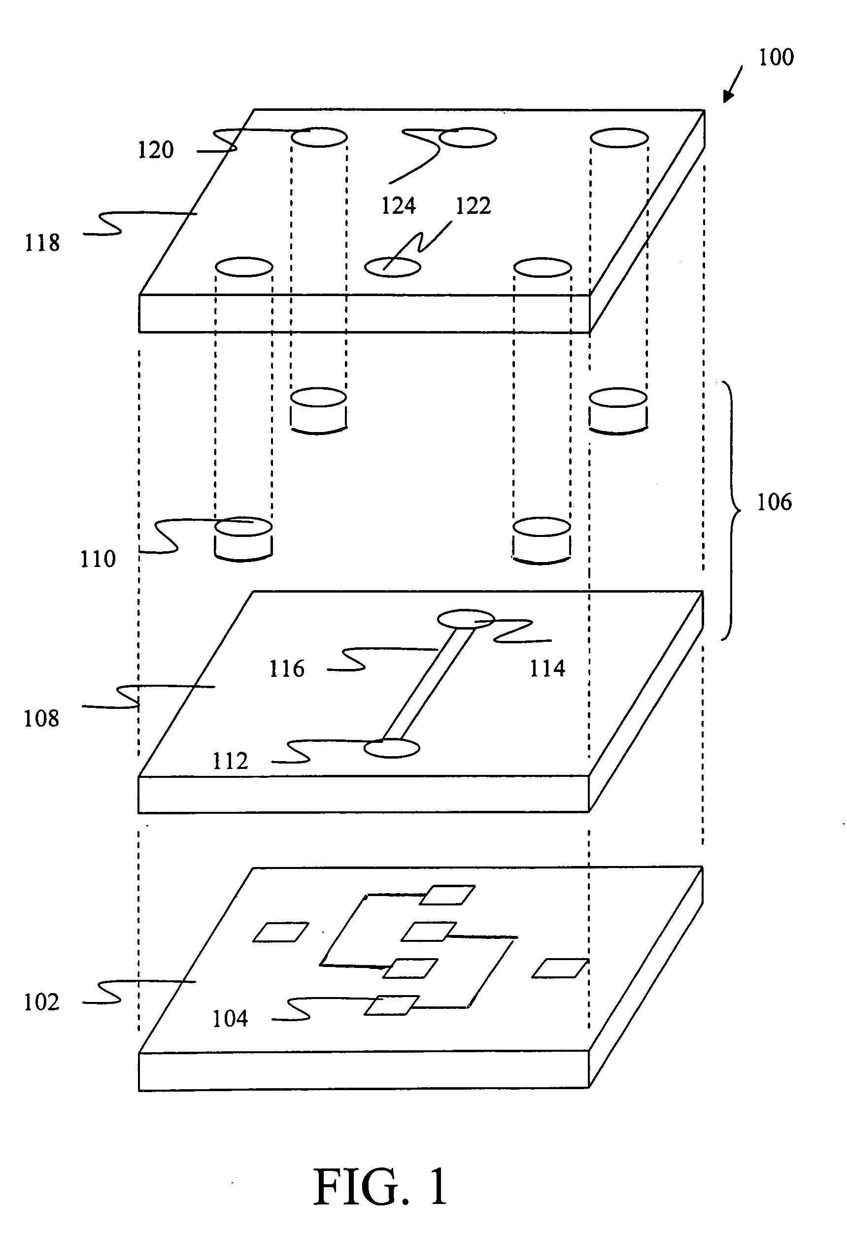
[0037] According to a first embodiment of the present invention illustrated in FIG. 1, micro-electro-mechanical system (MEMS) device 100 comprises a substrate 102 comprising a plurality of electrodes 104 situated on an upper surface of substrate 102. The electrodes 104 include at least one anode and at least one cathode. A patterned structure 106 is situated over a portion or all of substrate 102. Patterned structure 106 comprises a first patterned layer 108 and a second patterned layer 110. First patterned layer 108 comprises a first reservoir 112, a second reservoir 114, and a microchannel 116 connecting reservoirs 112 and 114 to one another. Microchannel 116 is situated directly over at least one of electrodes 104. Second patterned layer 110 is deposited on first patterned layer 108 and is configured as a plurality of cylindrical posts. An encapsulation membrane 118 is deposited on first patterned layer 108 and covers microchannel 116 and reservoirs 112 and 114. Encapsulation mem...
second embodiment
[0103] A micro-electro-mechanical system (MEMS) device 200 according to a second embodiment of the invention is illustrated in FIG. 7. Device 200 comprises a substrate 202 having an upper surface with a plurality of electrodes (not shown). Substrate 202 and electrodes may comprise like materials and characteristics and may serve like functions as substrate 102 and electrodes 104 described above in the first embodiment. Optionally, substrate 202 may be PYREX.
[0104] A patterned structure 206 is situated on substrate 202. Patterned structure 206 may comprise like materials (e.g., SU-8) and characteristics and may serve like functions as patterned structure 106 described above. Patterned structure 206 comprises a patterned layer 208 and a ridge (or “micro-knife edge”) 210. Patterned layer 208 defines a microchannel 216 aligned with at least one of the electrodes. Patterned layer 208 further defines an inlet / outlet reservoir 212. Ridge 210 is situated on the upper surface of patterned l...
third embodiment
[0111] A third embodiment of the invention is illustrated in FIG. 8. Generally, the materials, structures and functions of components 302, 306, 308, 310, 312, 316, 318, and 322 are the same components 202, 206, 208, 210, 212, 216, 218, and 222, respectively. In the interest of brevity, their descriptions are incorporated by reference and will not be repeated.
[0112] A reactive layer (not shown in FIG. 8) is deposited over the first electrode in microchannel 316. The reactive layer of the third embodiment may comprise the same materials (e.g., chitosan) and is capable of conjugation to the same molecules as described above in connection with the first embodiment.
[0113] Positioned below substrate 302 is a base frame 386 (e.g., polycarbonate). Situated on top of sealing layer 318 are, in order from lowest to highest, upper substrate layer 380 (e.g., PLEXIGLASS), gasket layer (e.g., PDMS) 382, and a cover frame 384 (e.g., polycarbonate). O-ring seal 388 is positioned along port 322 bet...
PUM
| Property | Measurement | Unit |
|---|---|---|
| Force | aaaaa | aaaaa |
| Electric potential / voltage | aaaaa | aaaaa |
| Compressibility | aaaaa | aaaaa |
Abstract
Description
Claims
Application Information