
Sending and/or receiving serial data with bit timing and parallel data conversion

Active Publication Date: 2005-10-20
SEMICON COMPONENTS IND LLC
View PDF23 Cites 39 Cited by
  • Summary
  • Abstract
  • Description
  • Claims
  • Application Information

AI Technical Summary

Benefits of technology

[0028] In another preferred embodiment, a word load signal, sometimes referred to as a word clock, latches data into buffer registers. Between a serializer and a deserializerdeserializer

Problems solved by technology

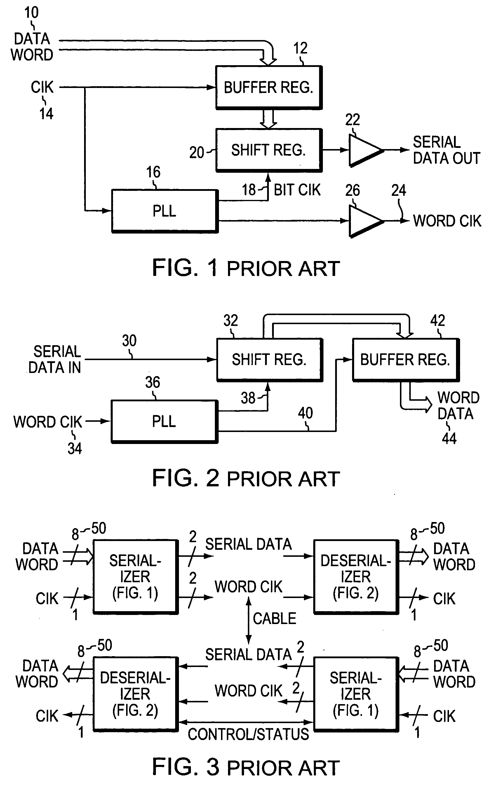
The serializer / deserializerdeserializers of FIG. 3 each contain a PLL that are common in such devices, but PLL's consume significant power, are complex, require long locking times, and occupy considerable chip real estate.
However, PLL's occupy significant real estate on a die and consume considerable power and time before being locked.
These parallel drivers consume high power and output high currents that create significant system noise.
In the newer designs, using sixty-four and one hundred and twenty-eight bits, the pins available on the packages become a design limitation.
However, the problem persists.
Prior art replacement of these buffer style circuits with serializers suffers from the power dissipation and complexity of the PLL's, the need for a reference clock, the lock time of the PLL, and the chip real estate occupied.
Up to the present time, serializing and de-serializing data entails using PLL's that are complex and costly of power chip space and time, as discussed above.

Method used


Image

  • Sending and/or receiving serial data with bit timing and parallel data conversion
  • Sending and/or receiving serial data with bit timing and parallel data conversion
  • Sending and/or receiving serial data with bit timing and parallel data conversion

Examples


Embodiment Construction

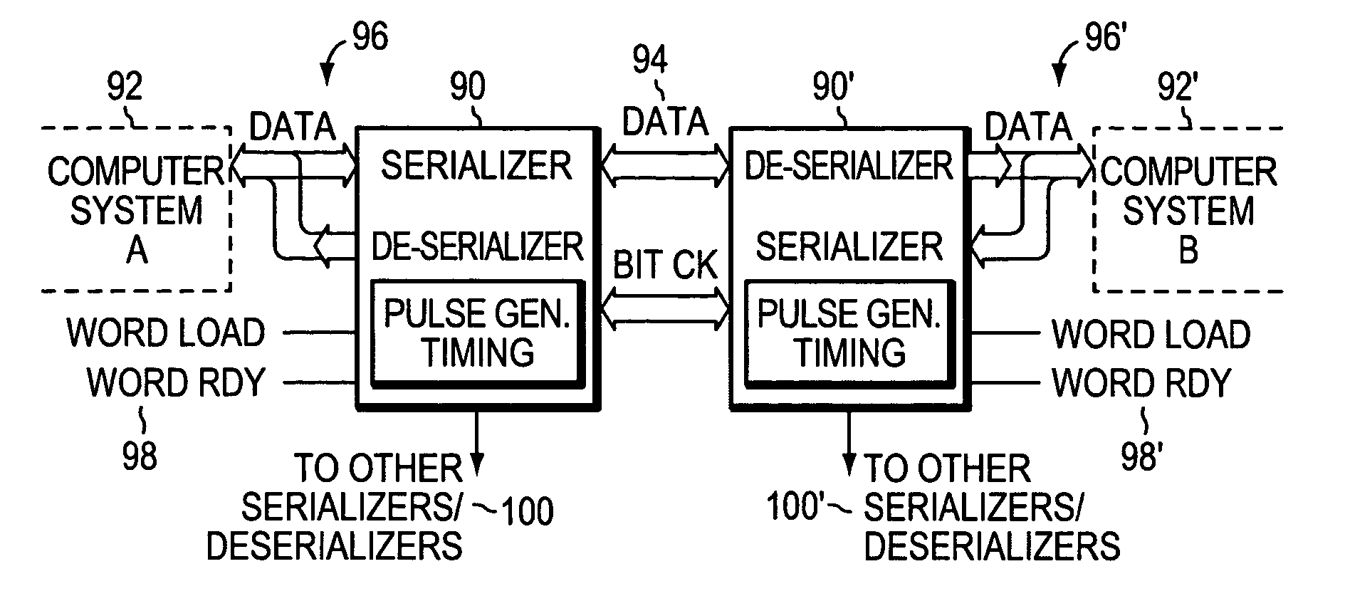
[0050]FIG. 7 is a generalized system block diagram embodying the present invention. As described below, many variations of FIG. 7 will be described. These implementations represent some of the configurations and operations where the present invention will be advantageous. But, the following descriptions are not exhaustive, as those practitioners in the art will know of or develop other configurations using the present invention.

[0051]FIG. 7 shows a computer system 92 that may be virtually any electronic system where parallel data is available for reading or writing, that is, besides usual computer systems, camera electronics, memory electronics, keyboards, scanners, print heads, wireless communications, etc. among other such systems known in the art that may employ the present invention.

[0052] It is helpful in describing preferred embodiments, to distinguish “synchronous” implementations where data is being sent continuously at a regular rate without using any handshaking. Data wo...


PUM


Abstract

A serializer and a deserializer are disclosed and shown operating singly or as a pair. The invention operates independently from any outside system reference clock. The inventive system provides an internal bit clock that serializes the data when sending and de-serializes the data when receiving. A bit clock or pulse travels with the data word bits to define when a bit is stable. The system uses word boundary bits operating with a bit clock to distinguish different data words, as described in the parent application. The system operates either synchronously or asynchronously with the base computer or other such digital system, including I / O devices. The invention finds use where new data to be sent is strobed into the serializer, but also where a change in the data bit content itself will cause the changed data to be loaded into the serializer and sent bit by bit. The system operates where new data is strobed or loaded by the serializer (not the base computer system) when the last data word has been sent. In this case a signal is generated when the last word has been sent in the serializer that causes new data to be loaded for sending. Half duplex and full duplex configurations as disclosed. Similar, corresponding operations occur at the deserializer.

Description

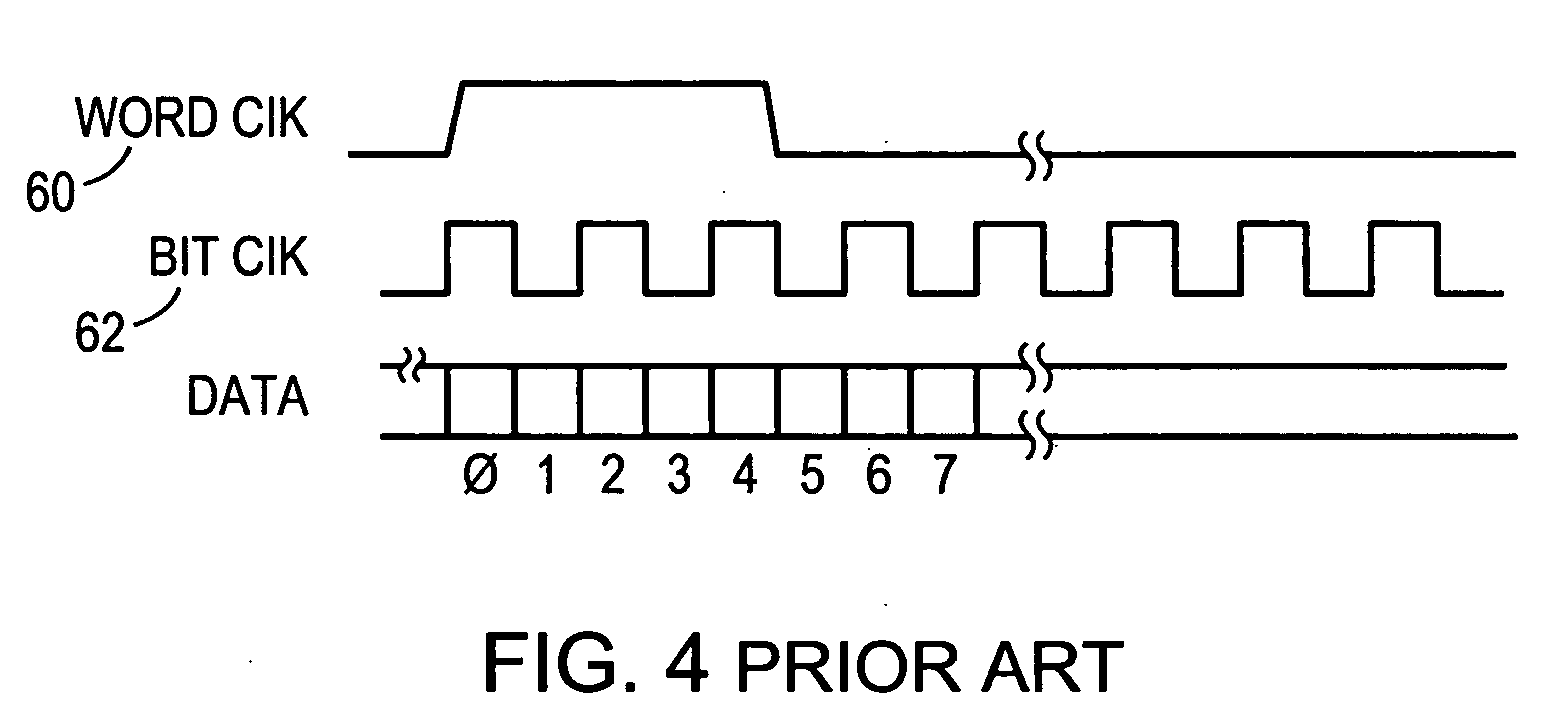
CROSS REFERENCE TO RELATED APPLICATIONS [0001] The present invention is related to an allowed application entitled, “BIT CLOCK WITH EMBEDDED WORD CLOCK BOUNDAR,” Ser. No. 10 / 802,436 filed on Mar. 16, 2004, and to an application entitled, “ARCHITECTURE FOR BIDIRECTIONAL SERIALIZERS AND DESERIALIZER,” Ser. No. 10 / 802,372 filed on Mar. 16, 2004. Both of these applications are owned by the same entity, and are both incorporated herein by reference.BACKGROUND OF THE INVENTION [0002] 1. Field of the Invention [0003] The present invention relates to data transmission, and more particularly to serializing and sending, bit by bit, data where the data word boundary is determined in order to properly receive and de-serialize the data. [0004] 2. Background Information [0005]FIG. 1 illustrates a known serializer in a block schematic form. A parallel data word 10 is loaded into a buffer register 12 with a word clock 14. The word clock 14 is also fed to a phase locked loop (PLL) or a delay locked ...

Claims


Application Information

Patent Timeline
IPC IPC(8): H03M7/00H03M9/00H04J3/06H04L7/00H04L7/033
CPCH03M9/00H04L7/033H04L7/0091H04J3/0614
Inventor FOWLER, MICHAEL L.BOOMER, JAMES B.
Owner SEMICON COMPONENTS IND LLC
Learn More