Transducer for bioacoustic signals

a bioacoustic signal and transducer technology, applied in the field of bioacoustic signal transducers, can solve the problems of increasing electrical noise, reducing sensitivity, and high equipment cost, and achieve good shielding and mechanical protection of diaphragms and connections, and reducing risk

Active Publication Date: 2005-10-20
3M INNOVATIVE PROPERTIES CO
View PDF9 Cites 39 Cited by
  • Summary
  • Abstract
  • Description
  • Claims
  • Application Information

AI Technical Summary

Benefits of technology

[0015] A further advantageous embodiment is in particular that the acoustical network consists of a cylindrical conduit having essentially the same diameter as the diaphragm. This corresponds to letting the diaphragm sit in the bottom of a well, which provides a good shielding and mechanical protection of the diaphragm and connections and reducing the risk that the closure of a port will change the frequency

Problems solved by technology

This type has in itself a good protection against extraneous airborne noises, but the sensitivity decreases and the electrical noise increases very much in the lower end of the frequency range of interest, unless the inertial mass is increased to a value in which it unavoidably influences the actual measurement.
This makes the equipment expensive and causes a need for re-programming if the sen

Method used


Image

  • Transducer for bioacoustic signals
  • Transducer for bioacoustic signals
  • Transducer for bioacoustic signals

Examples


Embodiment Construction

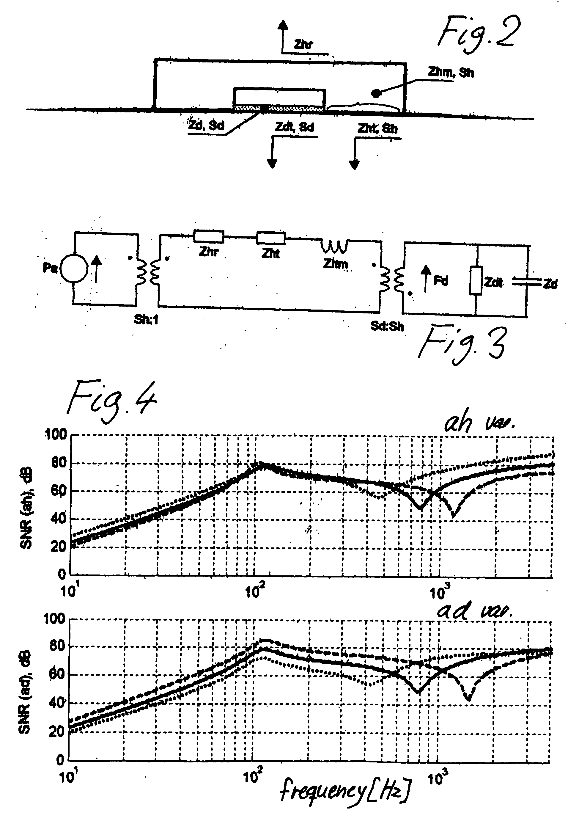
[0037] In the equivalent circuits and the expressions of their properties, the following nomenclature is adhered to: [0038] Sh: Effective application area towards tissue of inactive transducer housing (e.g. calculated from the housing radius ah and the sensor diaphragm radius ad for concentrically distributed area elements) [0039] Zhr: Mechanical domain radiation impedance from transducer housing into the ambience calculated from Sh [0040] Zhm: Mechanical domain impedance of the transducer housing mass (Mh) [0041] Zht: Mechanical domain tissue impedance acting on transducer housing (calculated from Sh). Consists of discrete elements Rht, Mht and Cht [0042] Zha: Mechanical impedance of hand / arm holding the transducer housing (approximately 40 Ns / m) [0043] Sd: Effective application area towards tissue of active sensor diaphragm (calculated from the sensor diaphragm radius ad for concentrically distributed area elements) [0044] Zhr: Mechanical domain radiation impedance from sensor dia...


PUM


Abstract

In well-known electronic stethoscopic transducers the sensitive element is influenced by signals transmitted via the skin, and the rear side is enclosed in a housing to prevent airborne noise from reaching the sensitive element. According to the invention, an improved signal-to-noise ratio is obtained by letting the transducer be a piezoelectric transflexural diaphragm in contact with the skin, the rear side of the diaphragm communicating with the surronding air via an acoustical network, thereby receiving airborne noise which acts to counteract the influence of noise coming from the skin.

Description

BACKGROUND OF THE INVENTION [0001] 1. Field of Invention [0002] The invention concerns a transducer for bioacoustic signals comprising a transducer element having a front side and a rear side, the front side of which may establish an intimate contact with the surface of a body part, said surface being the transmitter of direct interior sound from the body, said transducer element being mounted in a housing subject to airborne noise, and having a surface surrounding the front side of said transducing element, said element and said surrounding surface being in intimate contact with the surface of said body part during use. [0003] 2. Description of Related Art [0004] Transducers for bioacoustic signals emanating from a body usually belong to two main types applied to an outside surface of the body. One type is a microphone in principle, in which the vibration of a delimited area of skin is picked up as pressure variations in the air surrounding the area of skin, usually the pressure va...

Claims


Application Information

Patent Timeline
IPC IPC(8): A61B7/04H04R1/46H04R17/00
CPCA61B7/04H04R1/46A61B2562/0204
Inventor ANDERSEN, BJOERN KNUD
Owner 3M INNOVATIVE PROPERTIES CO
Why Eureka
Try Eureka