Method and apparatus of controlling acceleration/deceleration of a vehicle
a technology of acceleration/deceleration and vehicle, applied in the direction of process and machine control, braking systems, instruments, etc., can solve the problems of rotating speed difference, power transmission member, operator/passenger of the vehicle may feel an unpleasant shock transmitted throughout the entire body of the vehicl
- Summary
- Abstract
- Description
- Claims
- Application Information
AI Technical Summary
Benefits of technology
Problems solved by technology
Method used
Image
Examples
1st embodiment
[0158]FIG. 6 is a block diagram showing an example in which the calculating device 50 as shown in FIG. 4 is applied to a vehicle 90 which is equipped with an internal combustion engine 10a of forced-ignition type as the drive source 10. In FIG. 6, although the internal combustion engine 10a is shown as a reciprocal type internal combustion engine of a single cylinder, any other types of internal combustion engines may be utilized.
[0159] Typically, the internal combustion engine 10a includes a connecting rod 101. A lower end portion of the connecting rod 101 is coupled to a crank pin 102. A crankshaft 103a which continues from the crank pin 102 is connected with a clutch 202 through a primary transmission 201. The primary transmission 201 is coupled to a main shaft 204 which is an input shaft of the transmission device 203 with the clutch 202 therebetween.
[0160] Inside the transmission device 203, the main shaft 204 is provided with an input shaft accelerating / decelerating device 6...
2nd embodiment
[0206]FIG. 13 is a block diagram showing an example in which the calculating device 50 as shown in FIG. 4 is applied to the vehicle 90 which is equipped with an electric motor 10b as the drive source 10. The electric motor 10b is connected with the clutch 202 through the primary transmission 201 at one end of the motor output shaft 103b. Further downstream configuration of the power transmission path is similar to the 1st Embodiment shown in FIG. 6 and, therefore, explanations of the other configurations and functions thereof will be omitted with similar reference numerals being designated to similar portions.
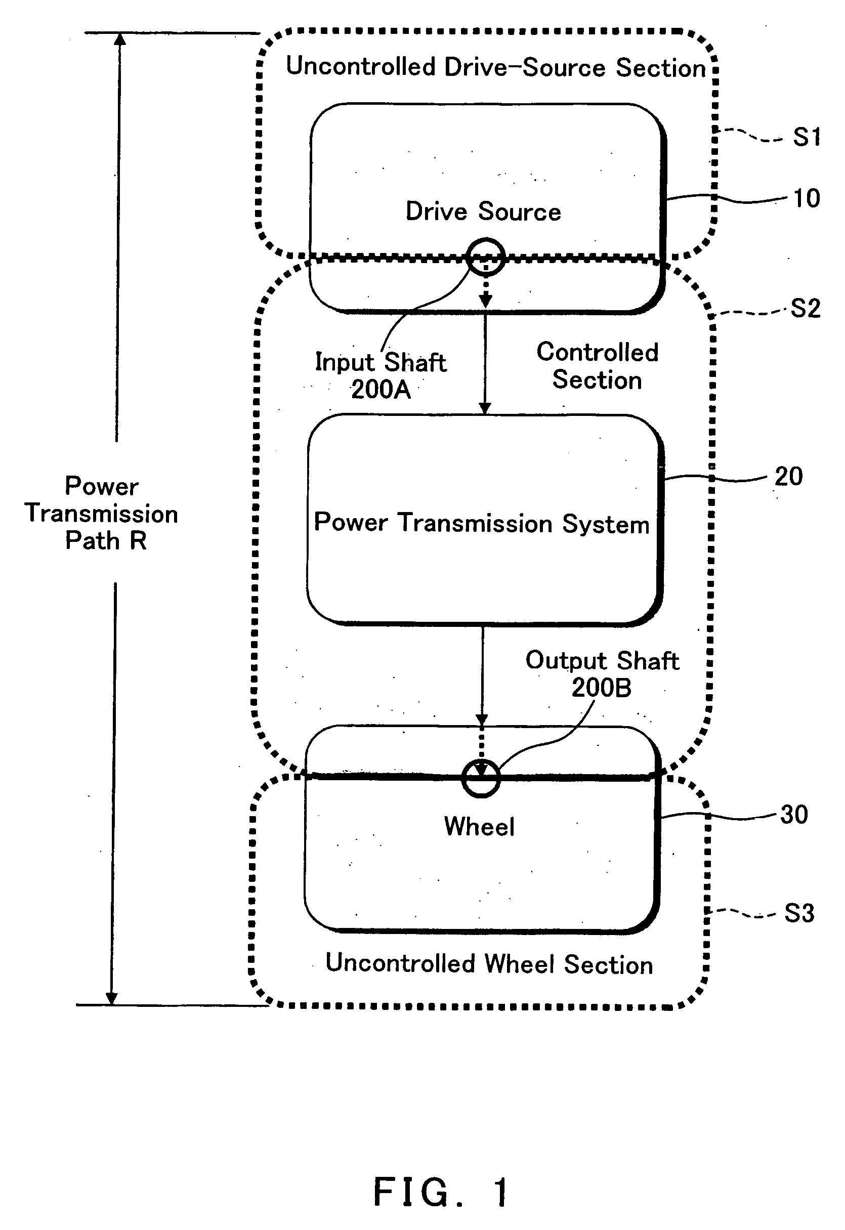
[0207] Also in this embodiment, the transmission device 203 surrounded with a thick dotted line in FIG. 13 is designated as the controlled section. The input shaft sensor 401 detects a rotational speed of the main shaft 204 which is the input shaft of the controlled section and transmits a detection result to the calculating device 50. The output shaft sensor 402 detects a rot...
3rd embodiment
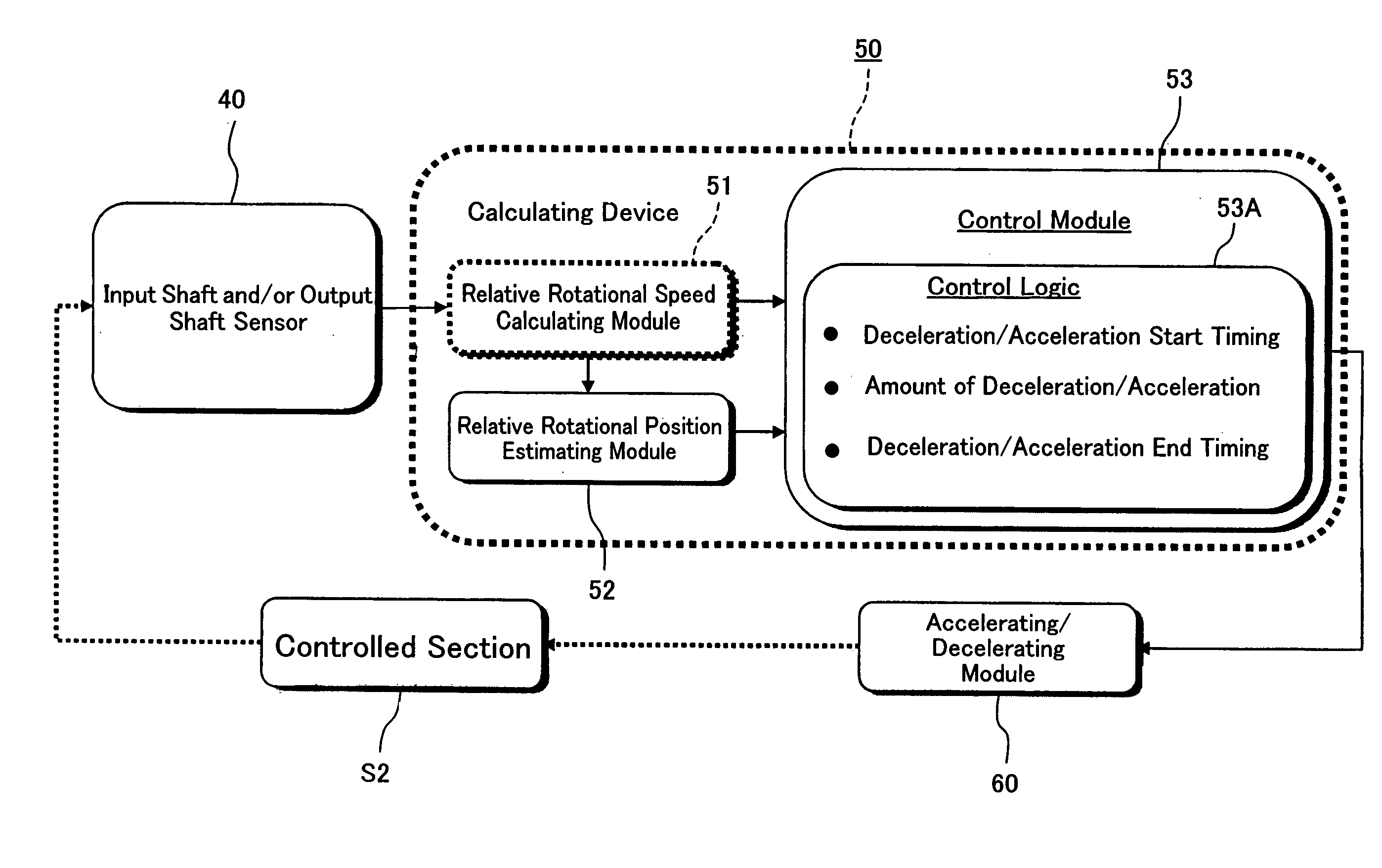
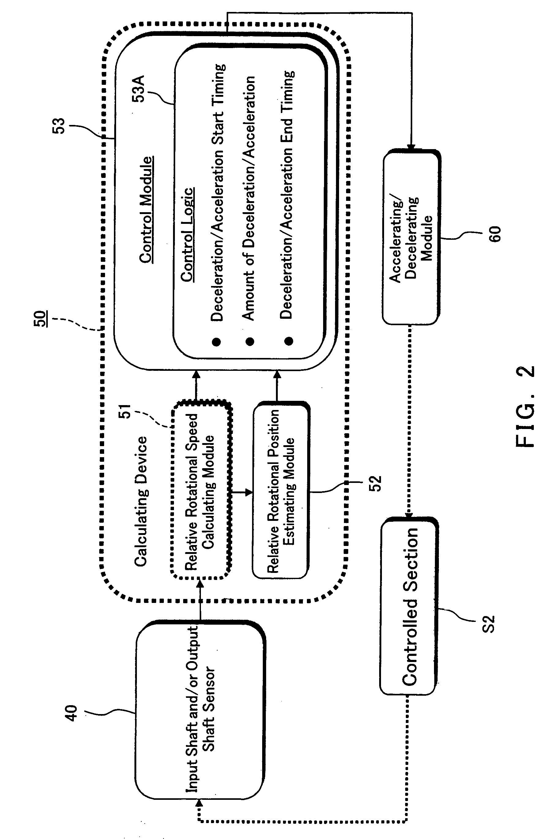
[0220] As shown in FIG. 14, the calculating device 50 according to this embodiment includes an output shaft rotational speed estimating module 54a as one example of the output shaft estimating module, instead of the low-path filter 54 shown in FIG. 5. With this configuration, a less delayed, precise estimation is possible as compared with the case where the low-path filter 54 is used. The output shaft rotational speed estimating module 54a estimates an output shaft rotational speed based on the input shaft rotational speed which is being inputted, and transmits the estimated output shaft rotational speed to the differentiator 51a as the relative rotational speed calculating module 51. Moreover, the output shaft rotational speed estimating module 54a is configured so that a relative rotational position estimated value outputted from the integrator 52a as the relative rotational position estimating module 52 is inputted into the output shaft rotational speed estimating module 54a.
[02...
PUM
 Abstract
Description
Claims
Application Information
 - R&D
- Intellectual Property
- Life Sciences
- Materials
- Tech Scout
- Unparalleled Data Quality
- Higher Quality Content
- 60% Fewer Hallucinations
Browse by: Latest US Patents, China's latest patents, Technical Efficacy Thesaurus, Application Domain, Technology Topic, Popular Technical Reports.
© 2025 PatSnap. All rights reserved.Legal|Privacy policy|Modern Slavery Act Transparency Statement|Sitemap|About US| Contact US: help@patsnap.com


