Sample processing system

Inactive Publication Date: 2005-10-27
CANON KK
View PDF0 Cites 9 Cited by
  • Summary
  • Abstract
  • Description
  • Claims
  • Application Information

AI Technical Summary

Benefits of technology

[0026] In the processing system, for example, the separating apparatus preferably ejects a stream of a fluid toward the separation layer while rotating the plate-like sample held horizontally to separate t

Problems solved by technology

However, the SOS technology has not been put into practical use to date because, e.g., a large amount of crystal defects are produced by lattice mismatch in the interface between the S

Method used


Image

  • Sample processing system
  • Sample processing system
  • Sample processing system

Examples


first embodiment

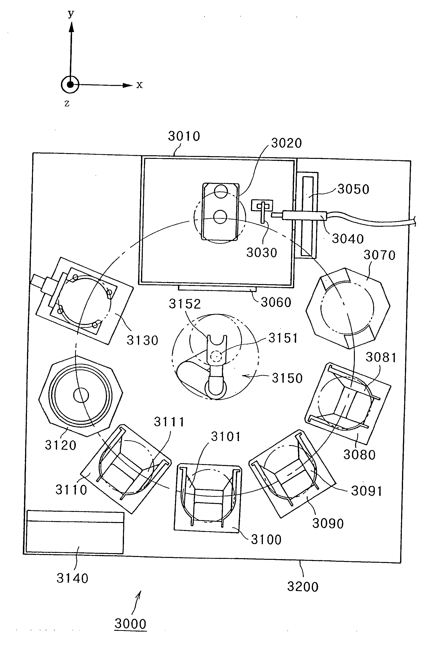
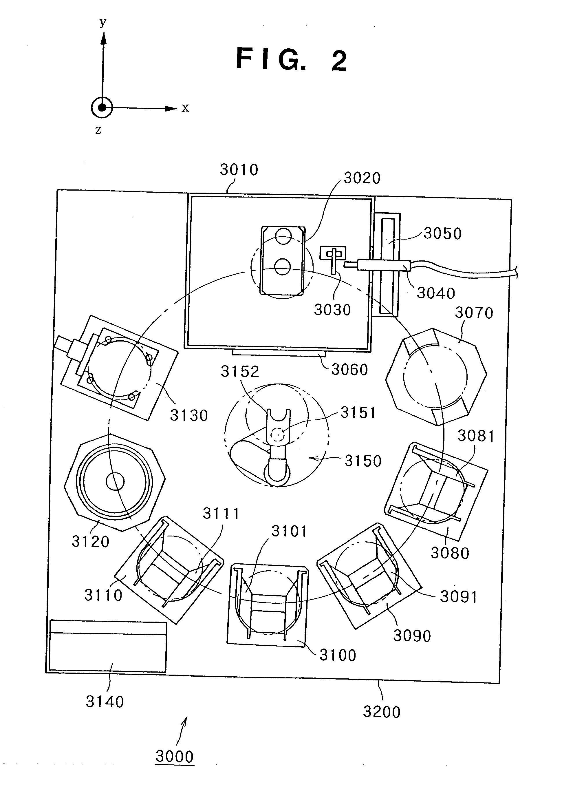
[0105]FIG. 2 is a plan view showing the schematic arrangement of a processing system according to a first embodiment of the present invention. A processing system 3000 has a scalar robot 3150 at a predetermined position (e.g., at the center) on a support table 3200 as a conveyor mechanism for a bonded substrate stack. Various processing apparatuses for handling or processing a bonded substrate stack are disposed at equidistant positions separated from a driving shaft 3151 of the scalar robot 3150. More specifically, in this embodiment, a loader 3080, centering apparatus 3070, separating apparatus 3020, inverting apparatus 3130, cleaning / drying apparatus 3120, third unloader 3110, second unloader 3100, and first unloader 3090 are disposed at equidistant positions separated from the driving shaft 3151 of the scalar robot 3150.

[0106] Before processing, a first cassette 3081 storing one or a plurality of bonded substrate stacks is placed on the loader 3080, an empty second cassette 309...

second embodiment

[0136]FIG. 14 is a plan view showing the schematic arrangement of a processing system according to the second embodiment of the present invention. In a processing system 6000, a bonded substrate stack is extracted from a cassette and separated, and separated substrates are cleaned and dried, classified, and stored in cassettes.

[0137] This processing system 6000 has, as a bonded substrate stack conveyor mechanism, a scalar robot 6150 and horizontal driving shaft 6160 for linearly driving the scalar robot 6150. In the processing system 6000, the scalar robot 6150 is linearly moved along the horizontal driving shaft 6160, and simultaneously, a robot hand 6152 of the scalar robot 6150 is pivoted about a pivot shaft 6151 in a horizontal plane to move the robot hand 6152 close to or away from the pivot shaft 6151, thereby conveying a bonded substrate stack or separated substrate among the apparatuses.

[0138] The processing system 6000 has various processing apparatuses for handling or pr...

third embodiment

[0168]FIG. 15 is a plan view showing the schematic arrangement of a processing system according to the third embodiment of the present invention. In a processing system 6500, a bonded substrate stack is extracted from a cassette and separated, and separated substrates are cleaned and dried, classified, and stored in cassettes, as in the processing system 6000 of the first embodiment. However, the processing system 6500 is different from the first embodiment in that the system has two separating apparatuses.

[0169] This processing system 6500 has, as a bonded substrate stack conveyor mechanism, a scalar robot 6150 and a horizontal driving shaft 6160 for linearly driving the scalar robot 6150. In the processing system 6500, the scalar robot 6150 is linearly moved along the horizontal driving shaft 6160, and simultaneously, a robot hand 6152 of the scalar robot 6150 is pivoted about a pivot shaft 6151 in a horizontal plane to move the robot hand 6152 close to or away from the pivot sha...


PUM

PropertyMeasurementUnit
Angleaaaaaaaaaa

Abstract

This invention is to provide a processing system suitable for manufacturing an SOI substrate. A processing system includes a scalar robot for conveying a bonded substrate stack held by a robot hand, and a centering apparatus, separating apparatus, inverting apparatus, and cleaning/drying apparatus disposed at substantially equidistant positions from a driving shaft of the scalar robot. When the robot hand is pivoted about the driving shaft in the horizontal plane and moved close to or away from the driving shaft, a bonded substrate stack or separated substrate is conveyed among the processing apparatuses.

Description

[0001] This is a continuation-in-part application of U.S. patent application Ser. No. 09 / 434,741 filed on Nov. 5, 1999 entitled “SAMPLE PROCESSING SYSTEM”.BACKGROUND OF THE INVENTION [0002] 1. Field of the Invention [0003] The present invention relates to a sample processing system and, more particularly, to a processing system having a plurality of processing apparatuses for processing a sample. [0004] 2. Description of the Related Art [0005] A substrate (SOI substrate) having an SOI (Silicon On Insulator) structure is known as a substrate having a single-crystal Si layer on an insulating layer. A device using this SOI substrate has many advantages that cannot be achieved by ordinary Si substrates. Examples of the advantages are as follows. [0006] (1) The integration degree can be increased because dielectric isolation is easy. [0007] (2) The radiation resistance can be increased. [0008] (3) The operating speed of the device can be increased because the stray capacitance is small. ...

Claims


Application Information

Patent Timeline
IPC IPC(8): B32B1/00H01L21/00H01L21/677H01L21/687
CPCH01L21/67092Y10T156/1906H01L21/67167H01L21/67173H01L21/67276H01L21/67745H01L21/68707Y10S156/93Y10S156/941Y10S438/908Y10T156/1105Y10T156/19Y10T156/11Y10T29/49819H01L21/67161
Inventor YANAGITA, KAZUTAKAOHMI, KAZUAKISAKAGUCHI, KIYOFUMI
Owner CANON KK
Why Eureka
Try Eureka