Method for making a carbon nanotube-based field emission cathode device

a field emission cathode and carbon nanotube technology, applied in the manufacture of discharge tube main electrodes, electrode systems, electric discharge tube/lamps, etc., can solve the problems of difficult control of the structure of carbon nanotube arrays, difficulty in forming carbon nanotube arrays used for field emission, and inconvenient mass production of carbon nanotubes at a low cost, etc., to achieve the effect of improving the field emission efficiency

Active Publication Date: 2005-10-27
HON HAI PRECISION IND CO LTD +1
View PDF11 Cites 52 Cited by
  • Summary
  • Abstract
  • Description
  • Claims
  • Application Information

AI Technical Summary

Benefits of technology

[0010] Accordingly, an object of the present invention is to provide a method for making a carbon nanotube-based field emission cathode device which has an improved field emission efficiency.
[0011] Another object of the present invention is to provide a method for making a carbon nanotube-based field emission cathode device which is cost-efficient.
[0012] A further object of the present invention is to provide a carbon nanotube-based field emission cathode device which has an improved field emission efficiency.
[0017] Due to scoring the layer of conductive grease, first ends of at least some of the carbon nanotubes separated from the conductive grease, extending into more erent orientations, can emit electrons to the anode more efficiently. In addition, due to the step of sprinkling, large-area carbon nanotube-based field emission arrays can be obtained in low-cost. Further more, different design of the electrode on the base result in different carbon nanotube-based field emission cathode devices, which is suitable to used in different field emission devices.

Problems solved by technology

Arc discharge is widely used in forming carbon nanotubes, but it is not suitable for mass production of carbon nanotubes at a low cost, and further more it's difficult to control a structure of carbon nanotube arrays by this method.
However, forming carbon nanotube arrays used for field emission has other difficulties.
The carbon nanotubes formed by chemical vapor deposition methods usually twist at the top thereof, which reduces the efficiency of field emission.
Unfortunately the method for trimming the carbon nanotubes is usually complex or costly.
Further more, chemical vapor deposition methods are unsuitable for making uniform and large-area field emission cathode.
However, the step of peeling usually destroys the carbon nanotube array as well as the carbon nanotubes.
Thus the carbon nanotubes lied on the substrate is not beneficial to exert field emission feature of the carbon nanotubes.

Method used


Image

  • Method for making a carbon nanotube-based field emission cathode device
  • Method for making a carbon nanotube-based field emission cathode device
  • Method for making a carbon nanotube-based field emission cathode device

Examples


first embodiment

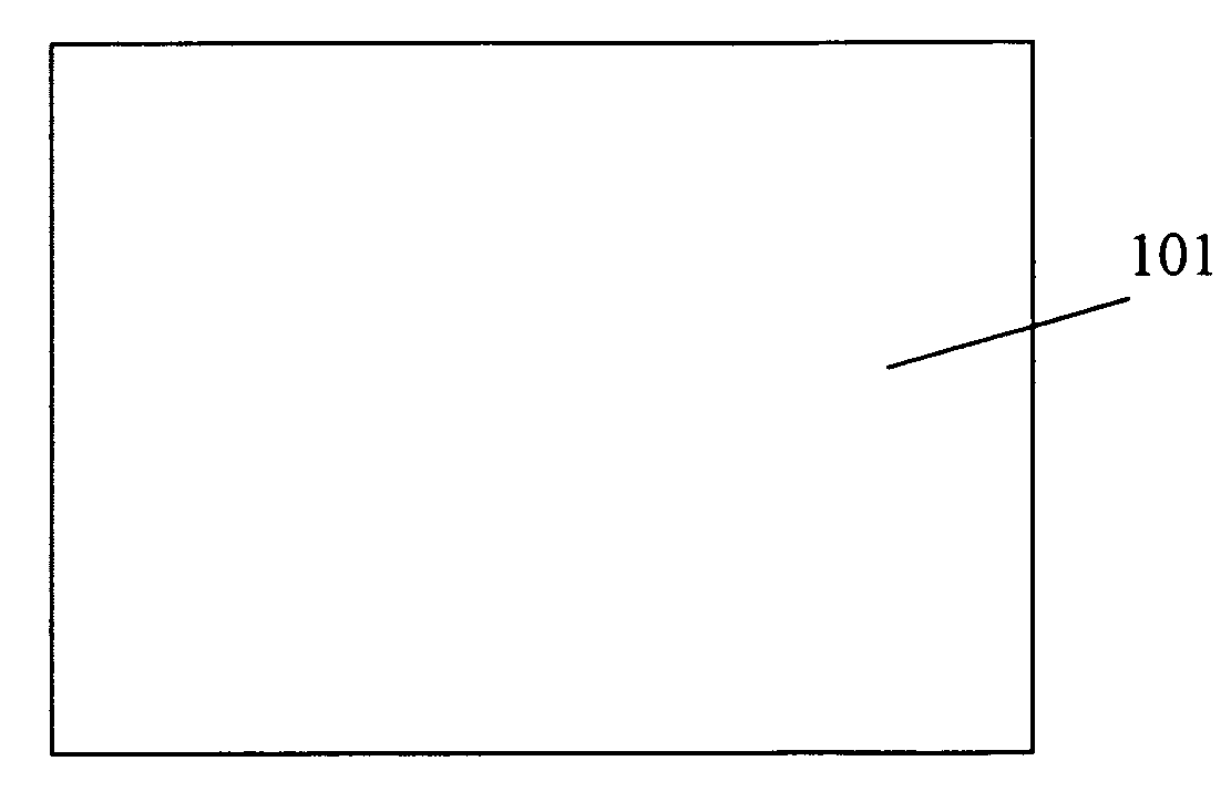
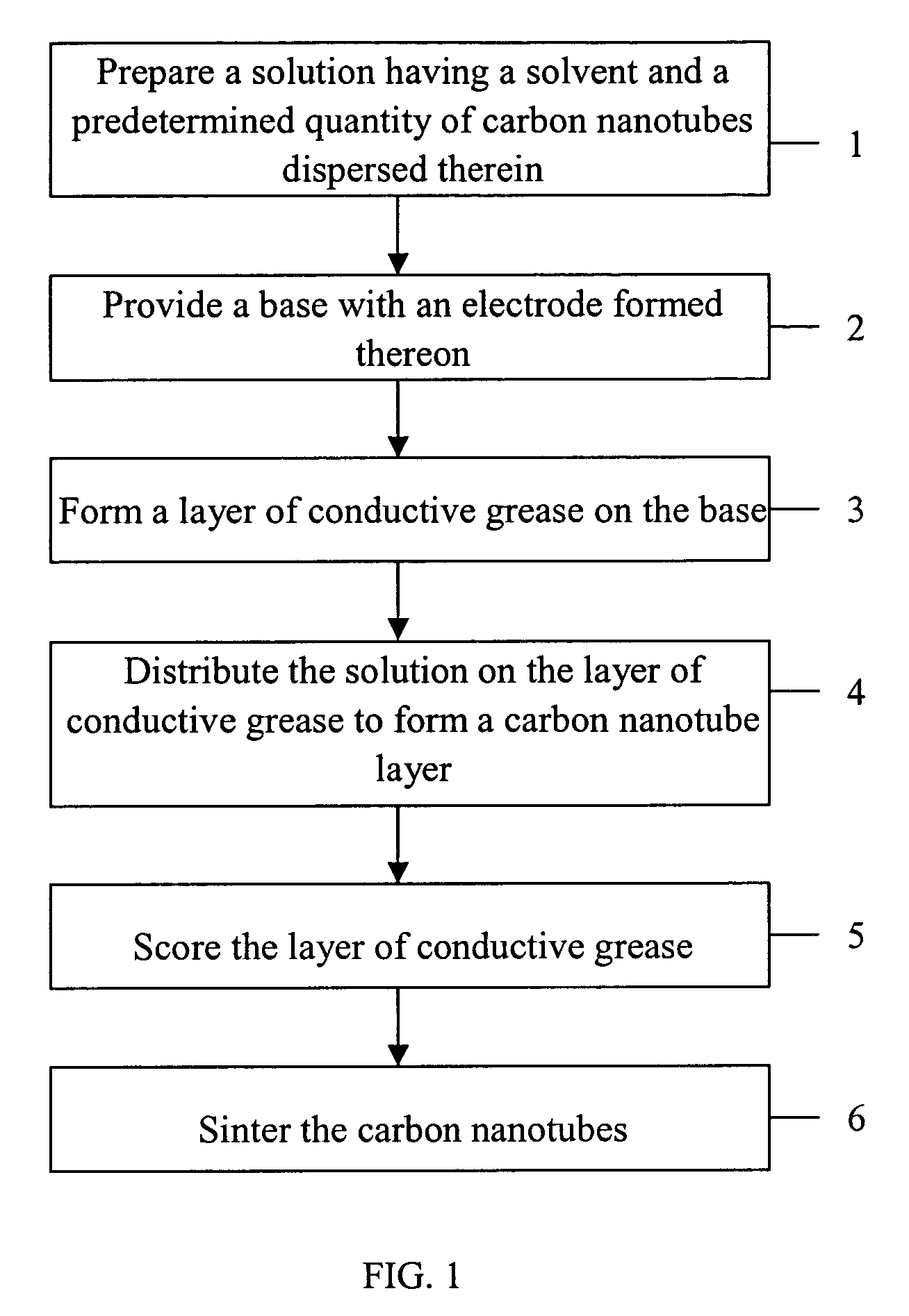
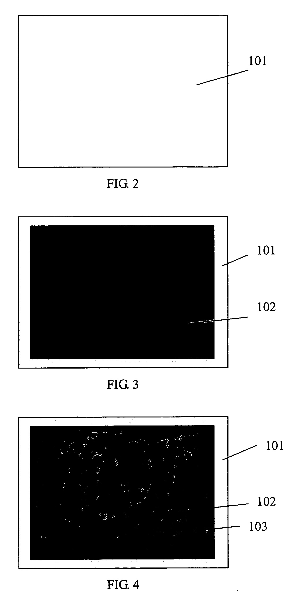
[0040] Referring to FIGS. 2 through 5, the present invention is a method for making a carbon nanotube-based field emission cathode device that is usable as a common electron source. Referring to FIG. 2, a base with an electrode 101 formed thereon is provided. The electrode 101 is a metallic membrane overlaid on the base. Referring to FIG. 3, a layer of conductive grease 102 is printed on the base, so that the electrode 101 is sandwiched between the base and the layer of conductive grease 102. Referring to FIG. 4, a carbon nanotube layer 103 is formed on the layer of conductive grease 102. Referring to FIG. 5, the layer of conductive grease 102 and the carbon nanotubes layer 103 are simultaneously scored into a regular array of grids. The carbon nanotubes are then sintered to fasten their opposite second ends onto the layer of conductive grease 102, thereby providing the carbon nanotube-based field emission cathode device. This cathode device having the single membrane electrode 101 ...

second embodiment

[0041] Referring to FIGS. 6 through 10, the present invention is a method for making a carbon nanotube-based field emission cathode device that can be used in a flat panel display device. The method comprises the following steps: preparing a solution having a solvent into which a predetermined quantity of carbon nanotubes is dispersed, providing a base with an electrode pattern formed thereon; forming a layer of conductive grease on the base; distributing the solution on the layer of conductive grease to form a carbon nanotube layer on the conductive grease; scoring the layer of conductive grease in order to make first ends of certain of the carbon nanotubes separate from the conductive grease; wiping off conductive grease that is not located on the electrode pattern; and sintering the carbon nanotubes, thereby attaining an effective carbon nanotube field emission cathode.

[0042] Referring to FIG. 6, a base with an electrode pattern 201 formed thereon is provided. The electrode patte...


PUM

PropertyMeasurementUnit
temperatureaaaaaaaaaa
voltageaaaaaaaaaa
conductiveaaaaaaaaaa

Abstract

A preferred method for making a carbon nanotube-based field emission cathode device in accordance with the invention includes the following steps: preparing a solution having a solvent and a predetermined quantity of carbon nanotubes dispersed therein; providing a base with an electrode (101) formed thereon; forming a layer of conductive grease (102) on the base; distributing the solution on the layer of conductive grease to form a carbon nanotube layer (103) on the conductive grease; and scoring the layer of conductive grease, for separating first ends of at least some of the carbon nanotubes from the conductive grease for attaining effective carbon nanotube field emission cathode.

Description

BACKGROUND OF THE INVENTION [0001] 1. Field of the Invention [0002] The present invention relates to a method for making a field emission cathode device, and more particularly to a method for making a carbon nanotube-based field emission cathode device. [0003] 2. Prior Art [0004] Carbon nanotubes are a novel carbonaceous material discovered by Iijima, a researcher of NEC corporation, in 1991. Relevant information was reported in an article by Iijima, entitled “Helical Microtubules of Graphitic Carbon” (Nature, Vol. 354, P56, 1991). Carbon nanotubes can transmit an extreme high electrical current and emit electrons at a very low voltage of less than 100 volts, which make it a very promising potential material for field emission applications. [0005] Arc discharge is widely used in forming carbon nanotubes, but it is not suitable for mass production of carbon nanotubes at a low cost, and further more it's difficult to control a structure of carbon nanotube arrays by this method. To ove...

Claims


Application Information

Patent Timeline
Patent Type & Authority Applications(United States)
IPC IPC(8): H01J1/02H01J1/304H01J9/02
CPCB82Y10/00H01J2201/30469H01J9/025H01J1/304
Inventor LIU, PENGWEI, YANGSHENG, LEI-MEILIU, LIANGFAN, SHOU-SHANHU, ZHAO-FU
Owner HON HAI PRECISION IND CO LTD
Why Eureka
Try Eureka