
Security barrier

a technology of security barrier and impact resistance, which is applied in the direction of roadway safety arrangements, roads, construction, etc., can solve the problems of insufficient mass, inadequate capability, and inability to effectively block a large or heavy vehicle, so as to reduce the number of unintended or unnecessary activations

Inactive Publication Date: 2005-10-27
VICUS TECH +1
View PDF27 Cites 23 Cited by
  • Summary
  • Abstract
  • Description
  • Claims
  • Application Information

AI Technical Summary

Benefits of technology

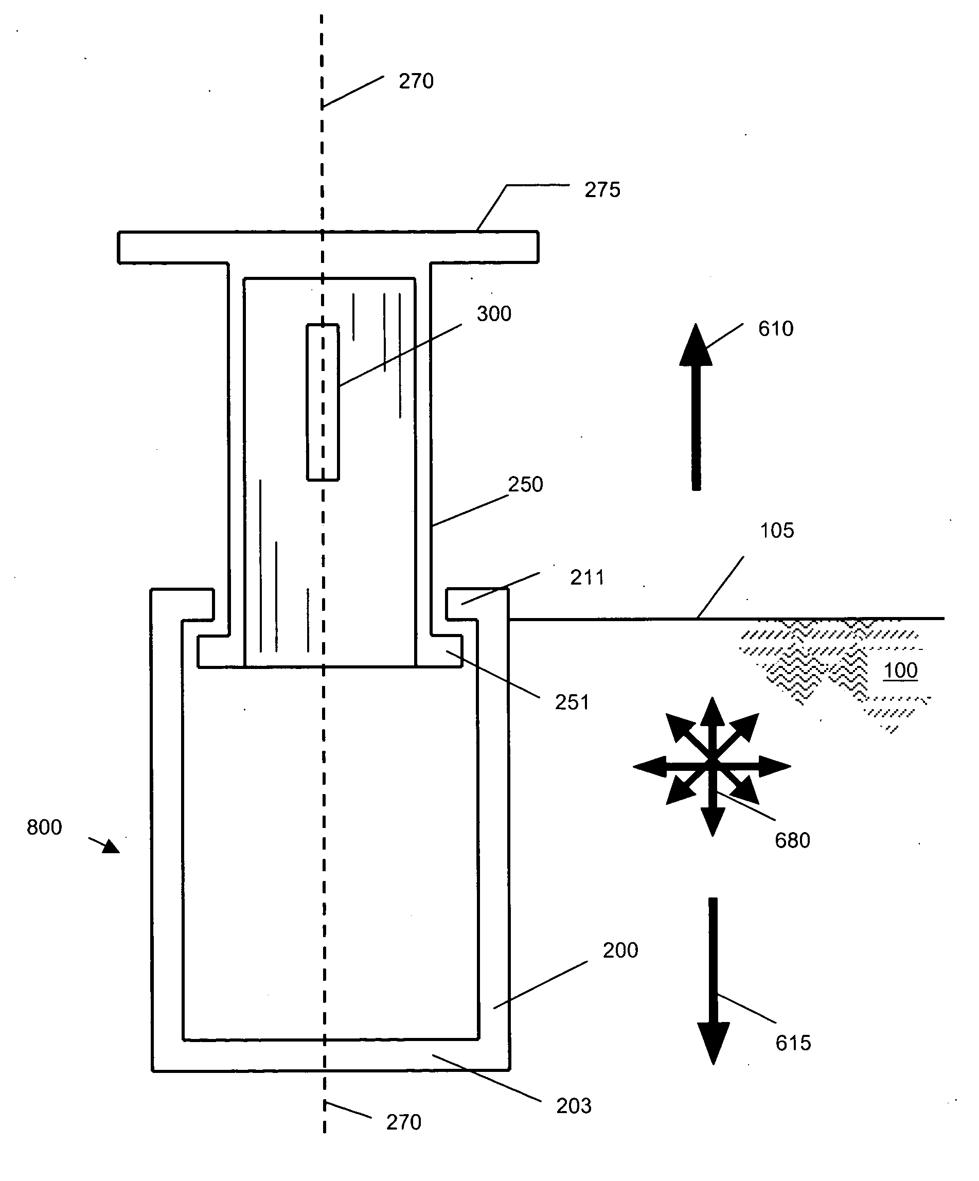
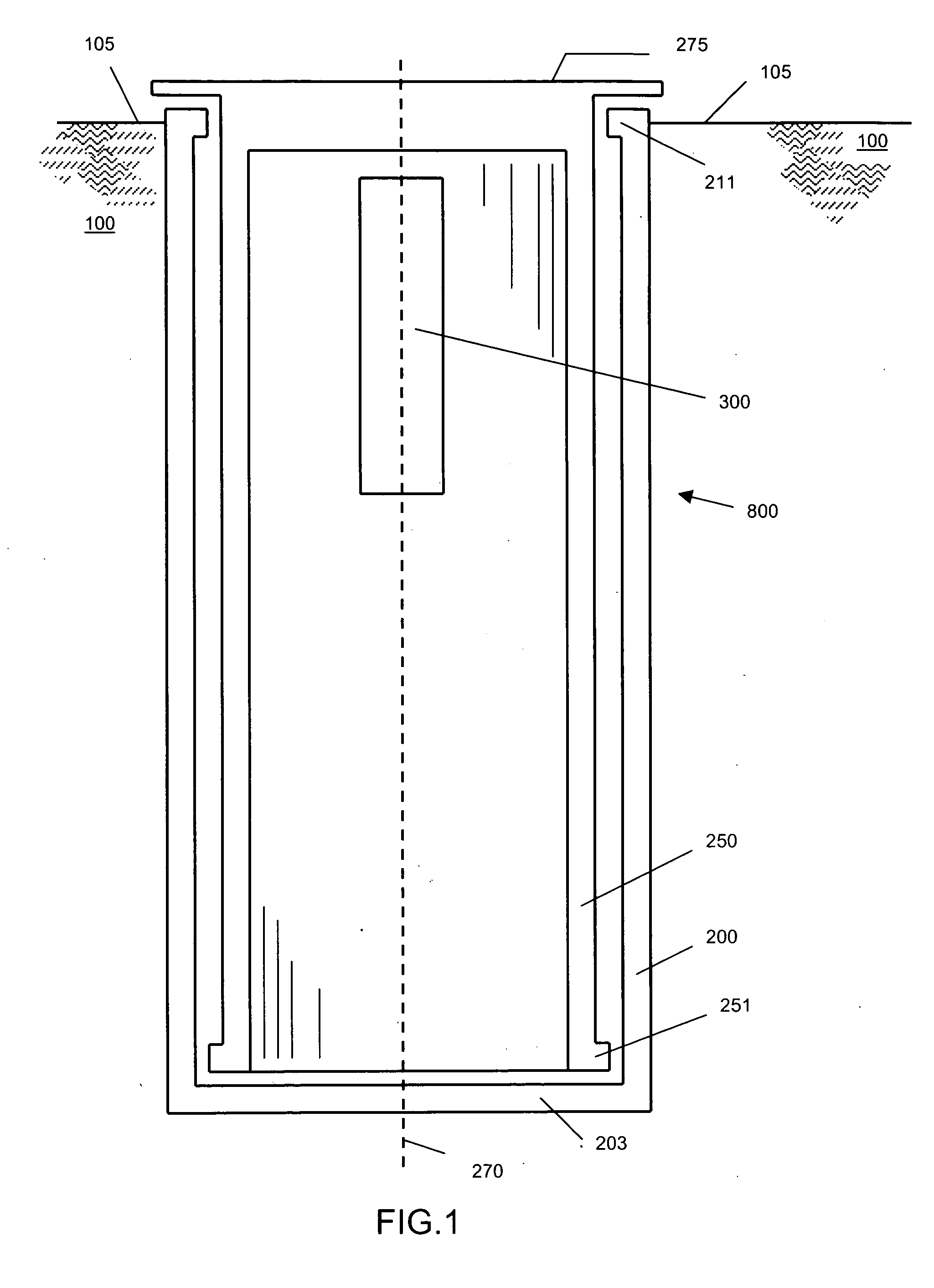
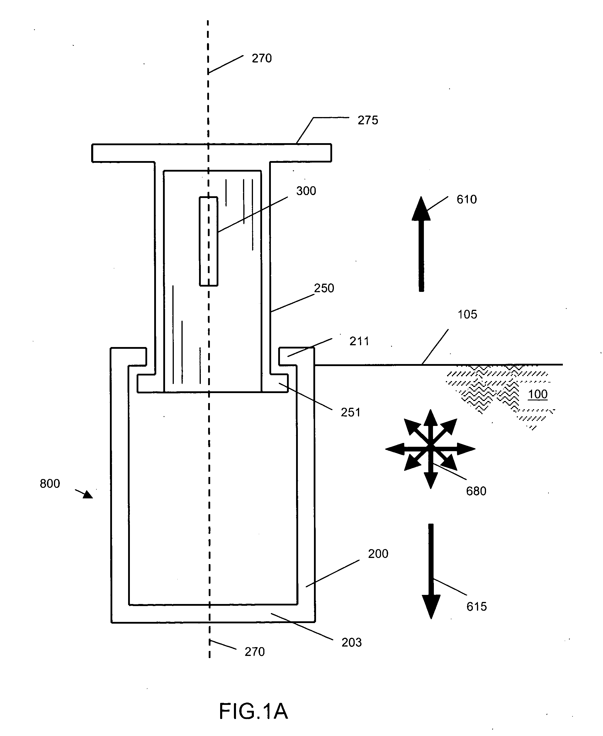
[0007] The invention pertains to a method and apparatus for erecting protective barriers / bollards utilizing a gas generation system (gas generator) to power the raising of the barrier structure to block the passage of a vehicle. The gas generator can be activated by a variety of means and independent of human intervention. The energy supplied by the gas generator allows deployment of the barrier from a stored to protective position at a speed significantly greater than achieved by existing methods. This allows the activation device to be placed close to the barrier, thereby permitting use of an automated barrier protective system in relatively confined spaces with minimized instances of unintended or unnecessary activation.
[0010] The activation of the barrier system may also be a motion detector, or a magnetic, strain, chemical, infra-red or radiation sensor. A remote sensor can signal activation by RF signal, requiring little power. The power source may be batteries or similar independent means, thereby minimizing deactivation of the protective system by power failure or sabotage.
[0013] It is a further object of the invention to provide a barrier that can be activated without human intervention.
[0014] It is another object of the invention to provide a barrier that can be quickly installed and removed
[0015] It is another object of the invention that the protective barrier can be portable and installed with minimal site preparation.

Problems solved by technology

The current raisable bollard systems have deficiencies that have been demonstrated based on current world events and terrorism threats.
These deficiencies are related to their dependency on human interaction to deploy the barrier of the bollard system, they are slow to activate, provide inadequate capabilities to prevent intrusion, and they are dependent on electric power or air systems which can be compromised by threats.
However, existing bollards or barriers that are raised to selectively block or control vehicle movement require either human intervention that retards deployment time, thereby diminishing effectiveness, or do not have sufficient mass to effectively block a large or heavy vehicle.

Method used


Image

  • Security barrier
  • Security barrier
  • Security barrier

Examples


Embodiment Construction

[0036] The above general description and the following detailed description are merely illustrative of the subject invention and additional modes, advantages and particulars of this invention will be readily suggested to those skilled in the art without departing from the spirit and scope of the invention. The requirements for the barrier system will vary based on the intended application. These variations are related to the denial requirements, the type of installation (permanent or temporary), location of the system, and the type of asset to be protected.

[0037] The invention proposed consists of an autonomous or automatic barrier or barrier restraint system, including automatic trigger sensors, communication devices to deploy the barrier component of the systems, automatic sensors to detect or activate the system, and an independent, self contained power supply to provide monitoring, activation, or alarm.

[0038] Deployment of the barrier component, regardless of the specific conf...


PUM


Abstract

An apparatus and method for installing and deploying a barrier utilizing one or more gas generators. The invention includes a barrier component installed beneath the ground surface or substantially parallel to the ground and raised by activation of the gas generator. The device can be trigger automatically without human intervention and thereby faster deployment of the barrier. The invention permits the passage of pedestrians, vehicles, etc. or activation into a barrier position.

Description

BACKGROUND OF INVENTION [0001] 1. Field of Use [0002] The invention pertains to a high strength impact resistant and rapidly deployable security barrier for the protection of persons and property from objects such as trucks and cars traveling at ground surface level. [0003] 2. Prior Art [0004] Vehicle and traffic barricades are well known and are in wide use for building and personnel security applications. These systems can be permanent or temporary. The barricades can be stationary or mobile with relatively rapid deployment for raising / lowering. The barricades can be wall like sections providing a resistive mass of reinforced concrete or hollow resinous plastic structures filled with water. Other types of traffic or vehicle control barriers are bollards that are fixed in position or that can be raised and lowered from the ground surface level. [0005] Bollards have been shown to be capable of incapacitating or stopping vehicles up to 7.5 tons GVW moving at speeds of 50 mph. The cur...

Claims


Application Information

Patent Timeline
Patent Type & Authority Applications(United States)
IPC IPC(8): E01C11/24E01F13/00E01F13/04E01F13/12
CPCE01F13/123E01F13/046
Inventor BURNS, ROBERTDARLING, DENNISHURLBURT, PAULKETNER, GARY
Owner VICUS TECH
Learn More