
Tubular carbon nano/micro structures and method of making same

a technology of carbon nanotubes and microstructures, applied in the field of tubular carbon nano/microstructures and the making of same, can solve the problems of cost prohibitive and slow tooling for the assembly of large-area nanopipettes of nanomaterials, and achieve the effect of reducing the cost of assembly and improving the quality of production

Inactive Publication Date: 2005-10-27
UNIV OF LOUISVILLE RES FOUND INC +1
View PDF5 Cites 10 Cited by
  • Summary
  • Abstract
  • Description
  • Claims
  • Application Information

AI Technical Summary

Benefits of technology

[0019] It is an object of the present invention to form nano tubular structures whereby the morphology can be controlled and fine tuned as needed.
[0025] It is an object of the present invention to produce nano structures which can be constricted by use of bimetallic strips or electrodes in electrical connection with an energy source in order to squeeze material out of the nano structure.
[0027] It is an object of the present invention to provide nanotube structures whereby the conical angle can be changed during the formation of the nanotube structures.
[0034] It is an object of the present invention to have the ability to tune the diameters from a few nm to as high as 25 microns, and control the morphologies and conical angles of these new class of the carbon tubular structures.

Problems solved by technology

However, these tools are still too slow and cost-prohibitive for the assembly of large-area nanopipettes of nanomaterials for device fabrication.

Method used


Image

  • Tubular carbon nano/micro structures and method of making same
  • Tubular carbon nano/micro structures and method of making same
  • Tubular carbon nano/micro structures and method of making same

Examples


Embodiment Construction

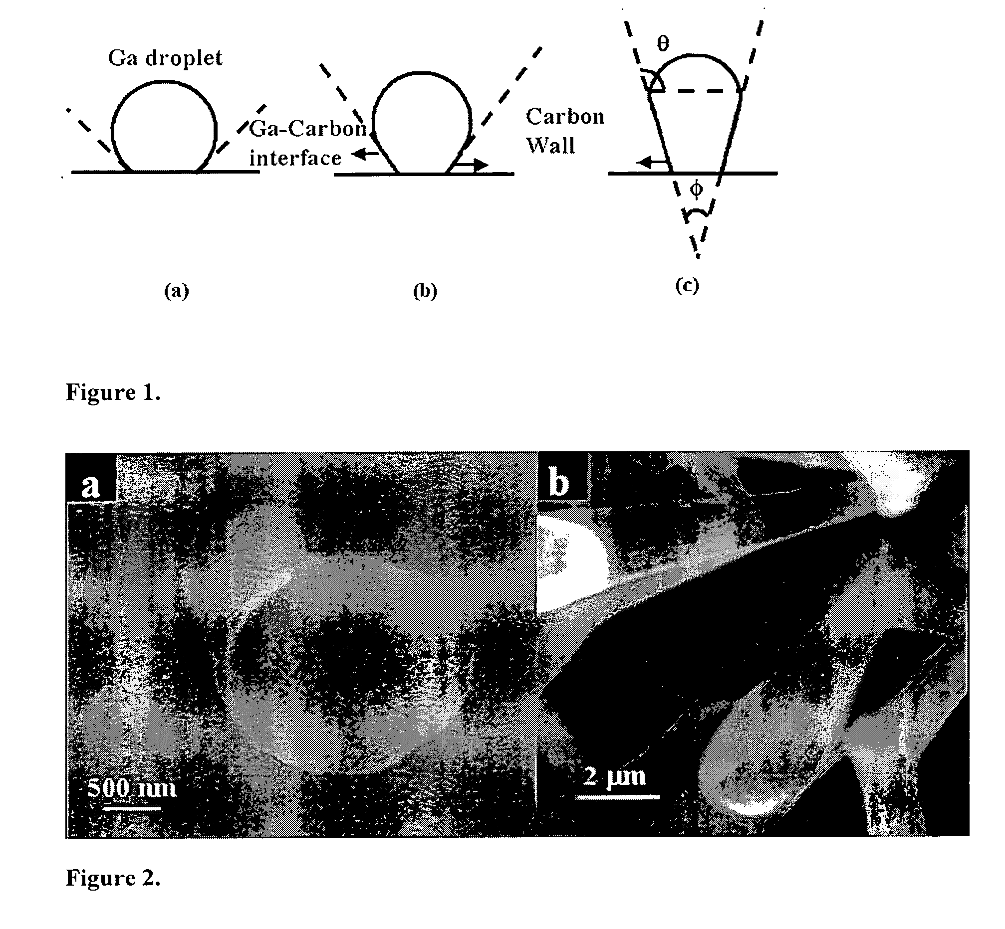
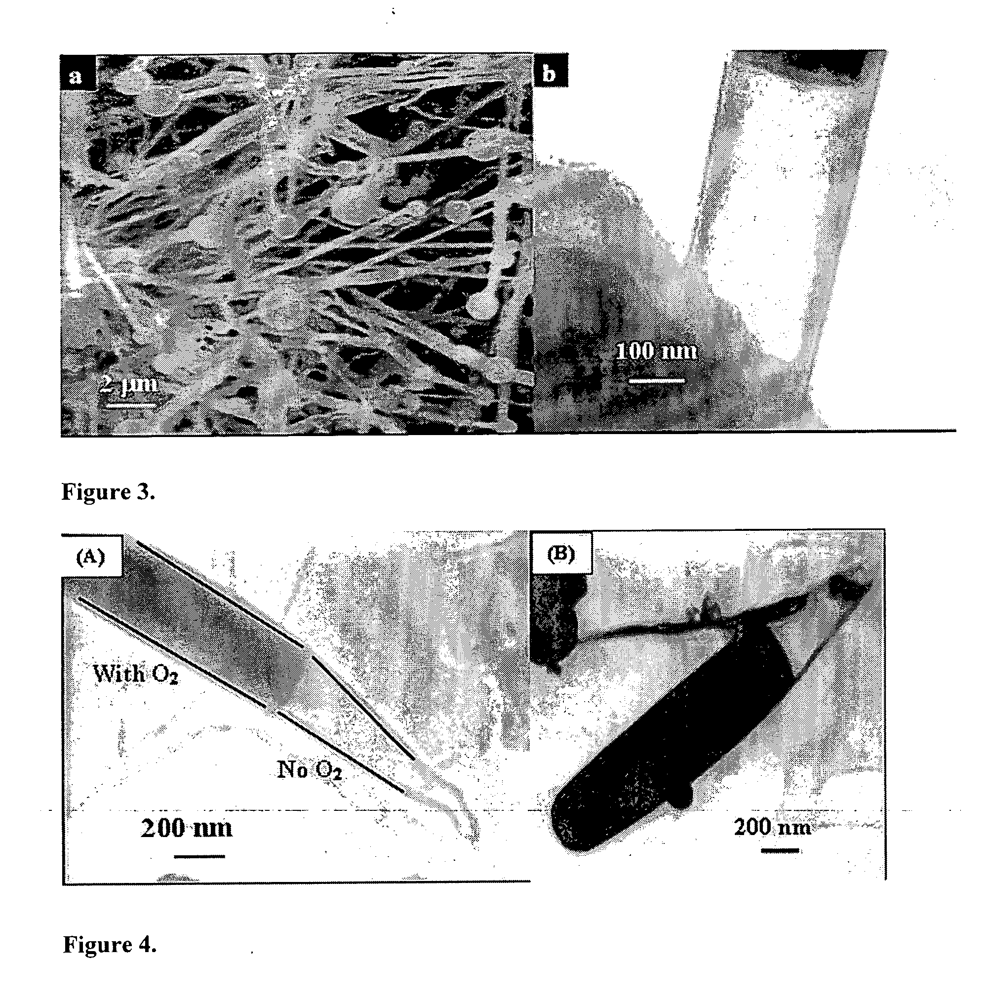
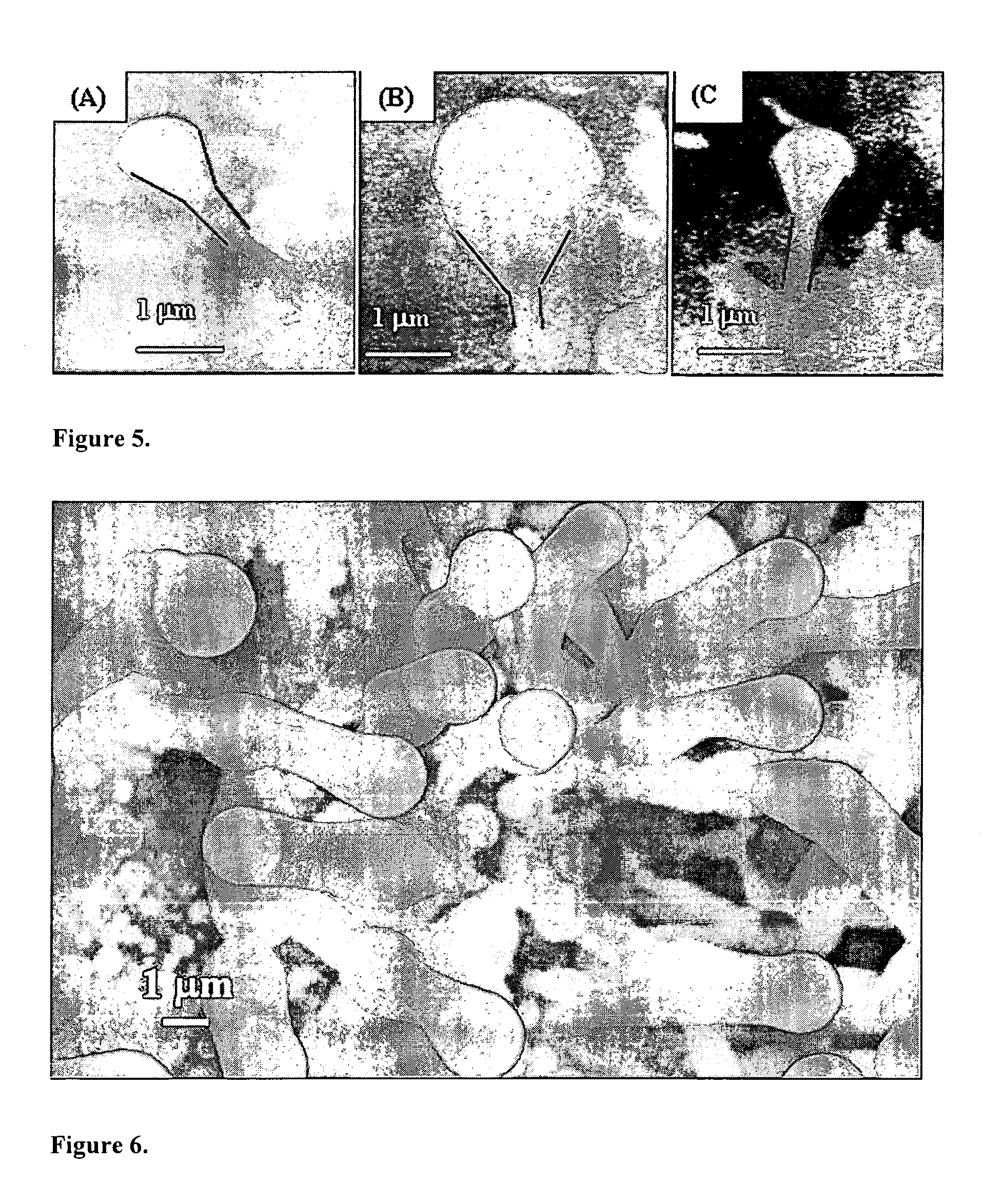
[0052] As illustrated in the figures, the present invention provides a technique to synthesize and control the morphology of tubular carbon nano structures including but not limited to cones, tubes, cone-on-tube (funnels), tube-on-cone, cone-tube-cone, n-staged structures (n>1), Y-junctions, multi-channeled junctions dumbbells and capsules.

[0053] The technique is based on our ability to change the wetting behavior of low melting metals such as gallium, indium and aluminum with carbon using different gas phase chemistries. For example, the contact angle between gallium and carbon can be reduced in the presence of activated oxygen or nitrogen. In the instant invention, the synthesis technique utilized a procedure of dosing the feed gases with oxygen or nitrogen or both at different stages of the growth to control and fine tune the internal diameters and morphologies of the carbon tubular structures. The gallium can be removed from the capsule by simply heating as shown in FIG. 16.

[0...


PUM

PropertyMeasurementUnit
diametersaaaaaaaaaa
thicknessaaaaaaaaaa
temperatureaaaaaaaaaa

Abstract

A method of synthesizing and controlling the internal diameters, conical angles, and morphology of tubular carbon nano / micro structures. Different morphologies can be synthesized included but not limited to cones, straight tubes, nozzles, cone-on-tube (funnels), tube-on-cone, cone-tube-cone, n-staged structures, multijunctioned tubes, Y-junctions, dumbbell (pinched morphology) and capsules. The process is based on changing the wetting behavior of a low melting metals such as gallium, indium, and aluminum with carbon using a growth environment of different gas phase chemistries. The described carbon tubular morphologies can be synthesized using any kind of gas phase excitation such as, but not limited to, microwave excitation, hot filament excitation, thermal excitation and Radio Frequency (RF) excitations. The depositions area is only limited by the substrate area in the equipment used and not limited by the process. The internal diameters of the carbon tubular structures can be varied from a few nm to as high as about 20 microns. The wall thickness is about 10-20 nm. The carbon tubular structures can be formed open on both ends are directly applicable to micro-fluidics. Gallium required for the growth of the carbon tubes can be supplied either as a thin film on the substrate or could be supplied through the gas phase with different precursors such as Tri-methyl gallium. Seamless Y-junctions with no internal obstructions can be synthesized without the need of templates. Multi-channeled junctions can also be synthesized without any internal obstructions. Gallium that partially fills the carbon structures can be removed from the tubes by simple heating in vacuum at temperature above 600°.

Description

[0001] This application claims priority from U.S. Provisional application Ser. No. 60 / 501,553 filed on Sep. 9, 2003.[0002] This application is part of a government project. The research leading to this invention was supported NSF through Contract / Grant No. 9876259. The United States Government retains certain rights in this invention.BACKGROUND OF THE INVENTION [0003] 1. Field of the Invention [0004] A method to synthesize and control the morphology of tubular carbon nano structures. Different morphologies of tubular carbon such as tubes, cones, nozzles, funnels, and multijunctioned tubes, can be synthesized reliably. The technique is based on the wetting behavior of gallium with carbon in different gas phase growth environments. [0005] 2. Description of the Prior Art [0006] The myriad structural manifestations and their material properties have made carbon nanostructures very interesting not only for potential applications but also for understanding carbon at the atomic scale. Seve...

Claims


Application Information

Patent Timeline
Patent Type & Authority Applications(United States)
IPC IPC(8): D01F9/12D01F9/127
CPCB82Y30/00Y10T428/2918D01F9/127
Inventor SUNKARA, MAHENDRA KUMARBHIMARASETTI, GOPINATH
Owner UNIV OF LOUISVILLE RES FOUND INC
Learn More