System for treatment of plantar fasciitis

a plantar fascia and support system technology, applied in the field of plantar fasciitis support system, can solve the problems of inconvenient and cumbersome elastic sock, poor comfort of patients, and difficulty in transferring patients, so as to achieve the effect of convenient application by patients

a plantar fascia and support system technology, applied in the field of plantar fasciitis support system, can solve the problems of inconvenient and cumbersome elastic sock, poor comfort of patients, and difficulty in transferring patients, so as to achieve the effect of convenient application by patients

US20050240139A1Active Publication Date: 2005-10-27APPLIED BIOKINETICS

Image

  • System for treatment of plantar fasciitis
  • System for treatment of plantar fasciitis
  • System for treatment of plantar fasciitis

Examples


Embodiment Construction

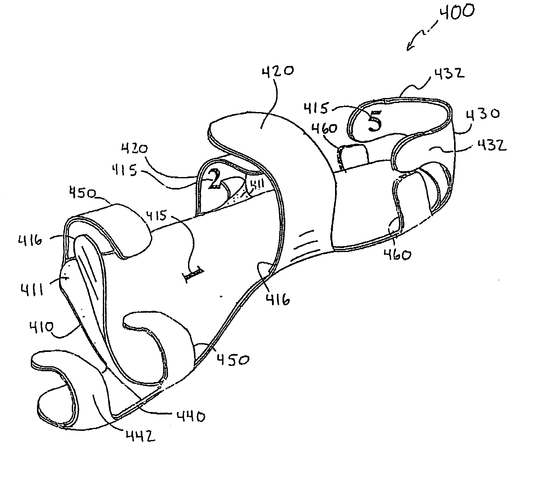
[0053]FIG. 3 illustrates a stretch resistant plantar fascia support system 400 in accordance with an embodiment of the present invention. The stretch resistant plantar fascia support system 400 includes a foot sole support 410, an adhesive layer 411, indicia 415, removable protective covers 416, arch straps 420, heel strap 430, heel strap tabs 432, toe strap 440, toe strap tab 442, front straps 450, and heel tabs 460.

[0054] The arch straps 420, the heel strap 430, the toe strap 440, the front straps 450, and the heel tabs 460 are connected to the foot sole support 410. The arch straps 420 project from the sides of the foot sole support 410 approximately midway along the longitudinal axis of the foot sole support 410. The heel strap 430 projects from the back edge of the foot sole support 410 and the heel strap tabs 432 project from the sides of the heel strap 430. The toe strap 440 projects from the front edge of the foot sole support 410 and the toe strap tab projects from a side ...


PUM


Abstract

An stretch resistant plantar fascia support system is provided. The stretch resistant plantar fascia support system is adhesively applied to the foot of a patient for providing relief from plantar fasciitis. A portion of the stretch resistant plantar fascia support system is adhesively attached to the bottom surface of the foot for reducing stress on the plantar fascia.

Description

BACKGROUND OF THE INVENTION [0001] The present invention generally relates to a stretch resistant plantar fascia support system. More particularly, the present invention relates to a stretch resistant plantar fascia support system that may be adhesively applied to a foot to provide relief from plantar fasciitis. [0002]FIG. 1 is a dissected bottom view of a human foot 100 provided to illustrate some of the parts of a plantar fascia 110 located in the bottom of the human foot 100. As shown in FIG. 1, the plantar fascia 110 extends from about the location of the heel 101 to about the location of the ball 102 of the foot. The plantar fascia 110 includes medial plantar fascia 120, superficial tracts 130, a central component of the plantar fascia 140, and a lateral component of the plantar fascia 150. The separate portions of the plantar fascia 110 act as a shock absorber while walking and transfer tensile forces along the bottom of the foot 100. [0003]FIG. 2 illustrates a simplified side...

Claims


Application Information

Patent Timeline
27 Oct 2005
Publication
US20050240139A1
IPC
A43B7/14; A61F5/00; A61F13/00; A61F13/06
CPC
A43B7/142; B65B5/10; A43B7/143; A43B7/1435; A43B7/144; A43B7/1445; A43B7/145; A43B7/1495
Inventors
BUSHBY, DONALD P.