Honeycomb structure, and honeycomb structure forming honeycomb

a technology of honeycomb and structure, applied in the direction of ceramic extrusion die, machine/engine, chemical/physical process, etc., can solve the problems of reducing affecting the production efficiency of honeycomb, and unable to exhibit sufficient isostatic strength. achieve high industrial applicability, high isostatic strength and thermal shock resistance, and high production efficiency

Active Publication Date: 2005-11-03
NGK INSULATORS LTD
View PDF13 Cites 12 Cited by
  • Summary
  • Abstract
  • Description
  • Claims
  • Application Information

AI Technical Summary

Benefits of technology

[0017] The present invention has been achieved in view of the above-described problems. The present invention aims at providing a honeycomb structure which excels in isostatic strength and thermal shock resistance and has such a high industrial applicability that the honeycomb structure can be manufactured at low cost, and a die for forming a honeycomb structure which enables the honeycomb structure to be manufactured without causing a forming failure.

Problems solved by technology

However, the above-mentioned progress of a decrease in thickness and an increase in porosity causes a decrease in isostatic strength and thermal shock resistance of the honeycomb structure, thereby causing damage to the partition wall as another problem.
However, since the cells of the honeycomb structure are provided at a uniform cell density in order to improve the thermal shock resistance or the heat exchange ratio, these honeycomb structures do not exhibit sufficient isostatic strength under practical environment in which vibration is continuously applied.
Therefore, these honeycomb structures cannot withstand long-term use.
However, since these honeycomb structures and the like merely aim at making the exhaust gas flow rate uniform, sufficient characteristics cannot be obtained for thermal shock resistance.
Therefore, these honeycomb structures and the like exhibit insufficient thermal shock resistance under high-temperature environment such as during the regeneration treatment when used as a filter due to damage to the partition wall or the like.
Moreover, since it is very difficult to manufacture a die corresponding to the complex shape at the boundary, these honeycomb structures and the like are rarely used in practical application.
However, since the partition walls of these honeycomb structures have a complicated bent structure, it is very difficult to manufacture a die for forming these honeycomb structures, whereby cost of the resulting honeycomb structure is increased to a large extent.
Therefore, these honeycomb structures are rarely used.
Therefore, a honeycomb structure having thin partition walls cannot be properly subjected to canning due to extremely low isostatic strength.
Therefore, if holes having the same inner diameter and the same material path length are provided to each cell pitch, the raw material extrusion speed is increased in the area in which the slit interval is small and the raw material extrusion speed is decreased in the area in which the slit interval is large, whereby a forming failure of the resulting honeycomb structure tends to occur.

Method used


Image

  • Honeycomb structure, and honeycomb structure forming honeycomb
  • Honeycomb structure, and honeycomb structure forming honeycomb
  • Honeycomb structure, and honeycomb structure forming honeycomb

Examples


example 1

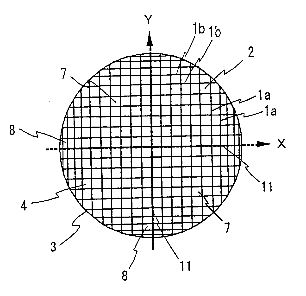
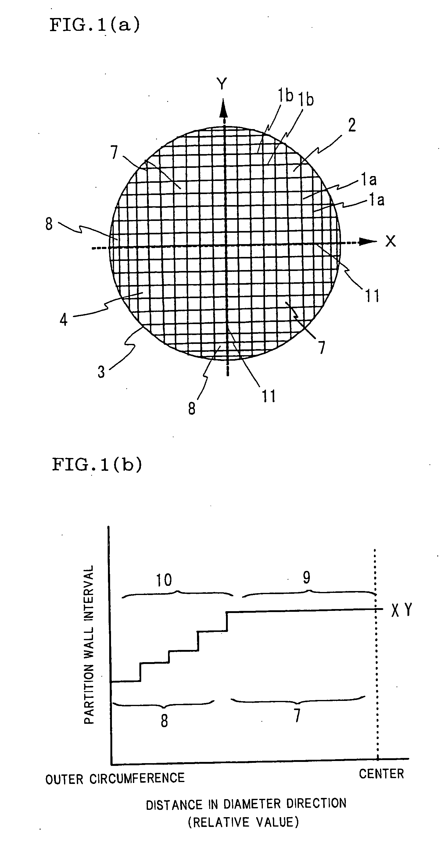
[0085] Kneaded clay containing a cordierite-forming raw material as a major component was prepared according to a conventional method. The resulting clay was extruded using a die for forming a honeycomb structure having a shape as shown in FIG. 1(a), dried, and fired to prepare a honeycomb structure. The resulting honeycomb structure was in the shape of a column having a diameter of about 130 mm and a length of 150 mm, in which the porosity was 25%, the thickness of the outer circumference wall was 0.3 mm, and the partition wall thickness was 0.06 mm. The outermost circumferential partition wall interval (first) was set to 0.85 mm, the next adjacent partition wall interval (second) was set to 0.88 mm, and the partition wall intervals for 10 cells were sequentially varied geometrically. The subsequent partition wall interval was fixed at 1.27 mm. Table 1 shows the partition wall intervals and the like in the 10-cell region, specifically, in a partition wall interval change region 10 ...

examples 6 to 9

[0089] A honeycomb structure was prepared in the same manner as in Example 1 except for changing the outermost circumferential partition wall interval to 0.7 mm, changing the partition wall interval in the partition wall interval fixed region to 1.27 mm, and varying the partition wall intervals for two cells or three cells at a variation ratio shown in Table 4. The resulting honeycomb structure was subjected to a thermal shock test by heating the honeycomb structure at 800° C. for 30 minutes in an electric furnace and removing the honeycomb structure from the electric furnace to observe the presence or absence of fracture of the honeycomb structure. The results are shown in Table 4. In the case where the constitution of the honeycomb structure and the thermal shock condition were as described above, since the honeycomb structure of Example 9 having a region in which the partition wall interval variation ratio was 0.6 fractured, it was confirmed that it is preferable that the partiti...

example 10

[0090] A cordierite honeycomb structure was prepared in the same manner as in Example 1 except for changing the partition wall thickness to 0.05 mm, changing the outermost partition wall interval (first) to 0.7 mm, sequentially varying the partition wall intervals for nine cells geometrically at a variation ratio shown in Table 5, and changing the partition wall interval in the partition wall interval fixed region to 1.04 mm.

TABLE 5 PartitionPartition(Cell sidewallwallCelllength / intervalintervalflatteningpartition wall(mm)variation ratioratiothickness)2Outermost0.730.041.4392circumferentialpartitionwalls (first)Second0.760.041.4392Third0.790.041.3392Fourth0.820.041.3392Fifth0.850.041.2392Sixth0.890.041.2392Seventh0.920.041.1392Eighth0.960.041.1392Ninth1.000.041.0392Partition wall1.04interval fixedregion


PUM

PropertyMeasurementUnit
thicknessaaaaaaaaaa
thicknessaaaaaaaaaa
porosityaaaaaaaaaa

Abstract

The present invention provides a honeycomb structure which includes a cell structure section 3 including a plurality of cells 2 partitioned by a plurality of partition walls 1a and 1b, and an outer circumferential wall section 4 surrounding the cell structure section 3. The cell structure section 3 includes a first partition wall group having the partition walls 1a positioned in parallel and a second partition wall group having the partition walls 1b which intersect the partition walls of the first partition wall group at right angles and are positioned in parallel, each of the partition walls 1a and 1b connecting two different locations of the outer circumferential wall section 4 through one continuous plane. In this honeycomb structure, the partition wall intervals of the partition walls 1a and 1b of each partition wall group positioned in parallel are varied stepwise in at least a part of the cell structure section 3, at least some of the cells have a rectangular cross-sectional shape, and all the partition walls 1a and 1b have such a ratio of the cell side length to the partition wall thickness that the partition wall can withstand pressure during canning. According to the present invention, a honeycomb structure which excels in isostatic strength and thermal shock resistance and has such a high industrial applicability that the honeycomb structure can be manufactured at low cost can be provided.

Description

TECHNICAL FIELD [0001] The present invention relates to a honeycomb structure and a die. More particularly, the present invention relates to a honeycomb structure provided with improved characteristics as a catalyst body, a filter, or the like by varying the partition wall intervals and a die therefor. BACKGROUND ART [0002] In recent years, various attempts have been made to improve purification performance of a honeycomb structure used as an exhaust gas purification catalyst body, filter, adsorbent, or the like in order to deal with tightened exhaust gas regulations. [0003] For example, attempts have been made to enable a honeycomb structure used as a catalyst body to exhibit a desired exhaust gas purification performance immediately after starting an engine by rapidly increasing the catalyst temperature to increase catalytic activity by reducing the thickness of the partition wall to reduce heat capacity. Attempts have also been extensively made to increase the porosity of the par...

Claims


Application Information

Patent Timeline
Patent Type & Authority Applications(United States)
IPC IPC(8): B01D46/00B01D46/24B01D53/88B01J35/04B28B3/20F01N3/022F01N3/28
CPCB01D46/0001Y10T428/24149B01D46/247B01D46/2474B01D53/885B01D2046/2481B01D2046/2496B01J35/04B28B3/269F01N3/0222F01N3/2828F01N3/2842F01N2330/06F01N2330/48F01N2340/00F01N2350/04F01N2470/00Y02T10/20Y10T428/24157B01D46/2466Y02T10/12B01D46/249B01D46/2498B01D46/2482
Inventor ICHIKAWA, YUKIHITO
Owner NGK INSULATORS LTD
Why Eureka
Try Eureka