Vibration isolating device

Inactive Publication Date: 2005-11-03
TOYO TIRE & RUBBER CO LTD
View PDF9 Cites 22 Cited by
  • Summary
  • Abstract
  • Description
  • Claims
  • Application Information

AI Technical Summary

Benefits of technology

[0011] For that reason, it is possible to diminish the dynamic spring constant in the fore-and-aft direction, and good vibration isolating characteristics can be exhibited to vibrations of a relatively small amplitude. This effect is particularly remarkable in cases where both front and rear stopper rubber portions are provided with the small cavity. Besides, upon vibration in a large amplitude, the small cavity is collapsed with its wall faces clinging to each other, and the spring force as a stopper becomes large, whereby it is possible to perform likewise a good stopper action as in the conventional device and to maintain a good durability, as well.
[0012] In particular where at least the rear stopper rubber portion is provided with the small cavity, the coupling member with the vibration generator is displaced rearwards upon acceleration or running of a vehicle at high speed with an engine revolution of 2500 rpm to 4000 rpm, and as a result, the vibration transmissi

Problems solved by technology

Upon running, however, due to the fact that the stopper rubber 105 abuts on the stopper member 107, the dynamic spring constant in the fore-and-aft direction is apt to become high and there is a tendency that a damping effect mainly to vibrations with a relatively small amplitude cannot be sufficiently obtained.
As a consequence, upon acceleration or running at high speed of a vehicle such as an

Method used


Image

  • Vibration isolating device
  • Vibration isolating device
  • Vibration isolating device

Examples


Example

[0021] Now the embodiments for carrying the invention into effect will be described with reference to the drawings.

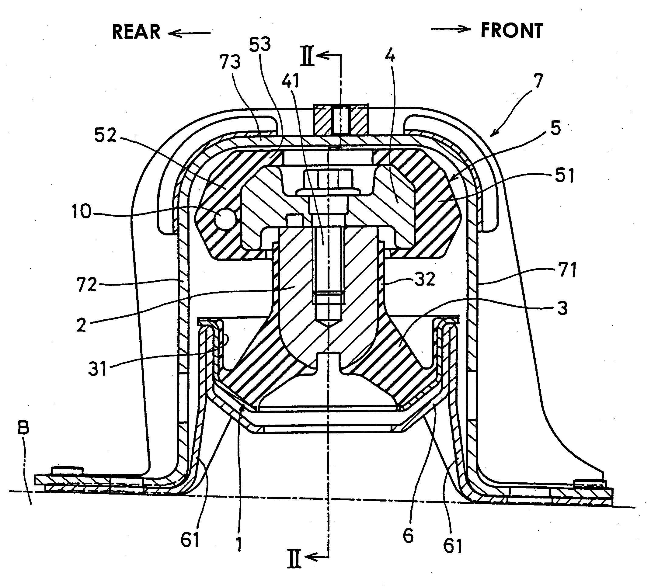
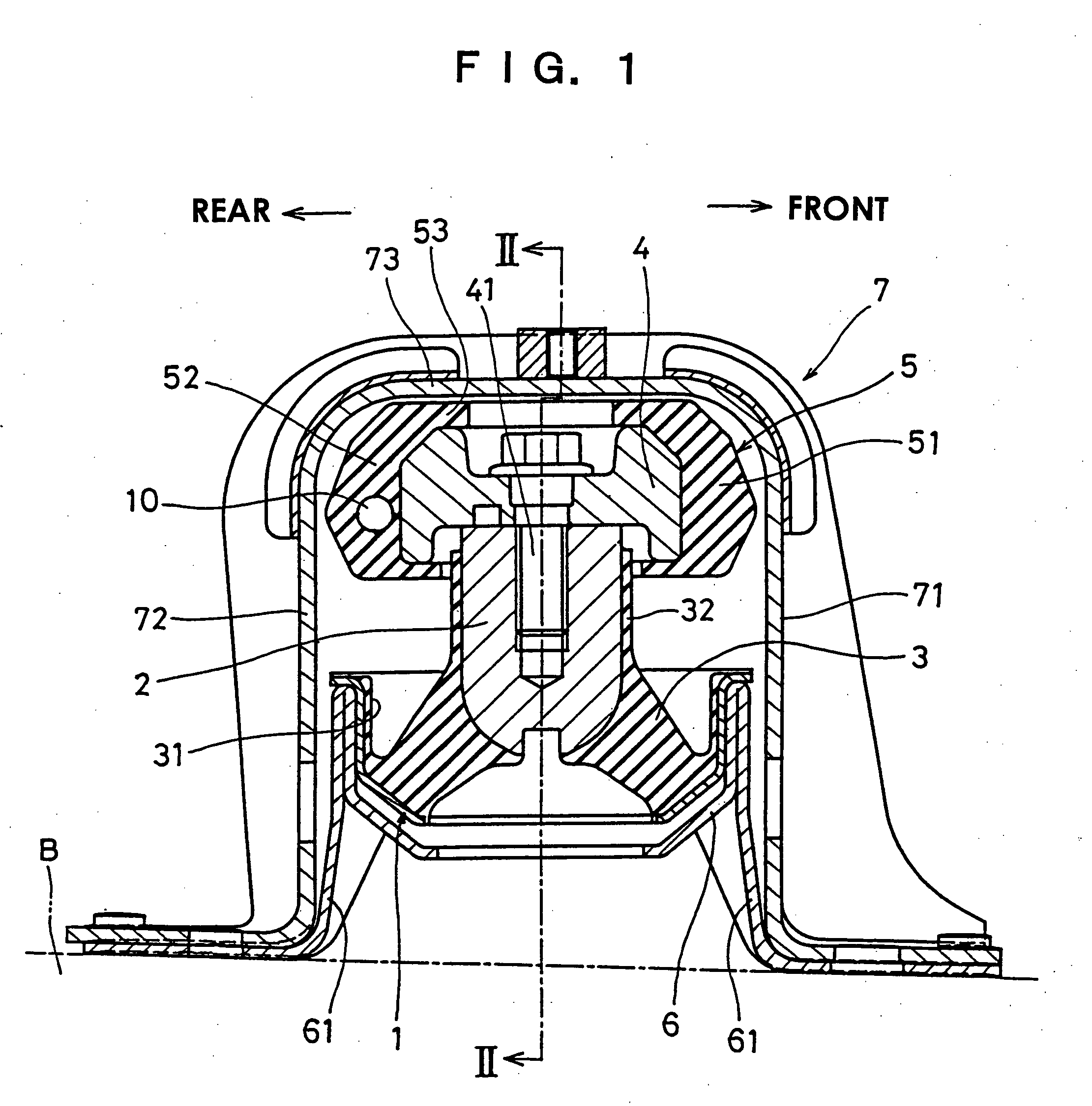
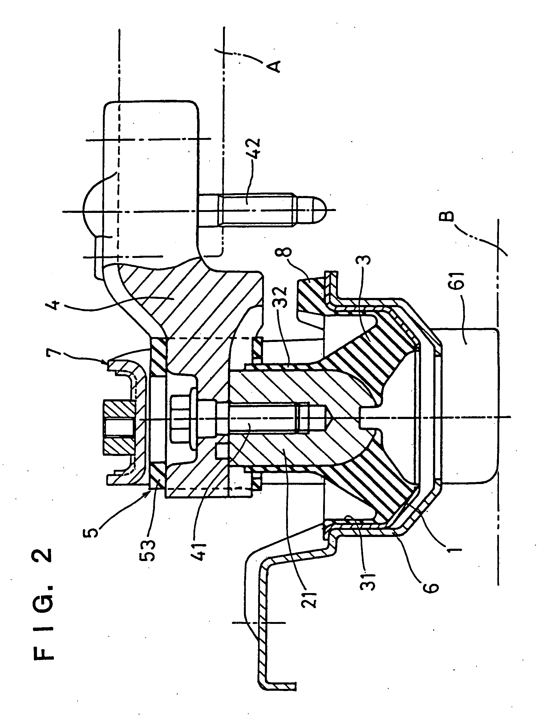
[0022]FIG. 1 is a longitudinal sectional view showing one example of a vibration isolating device relating to this invention; FIG. 2 is a longitudinal sectional view taken along II-II line of the preceding figure; FIG. 3 and FIG. 4 are transverse sectional views of a small cavity portion; FIG. 5 is a graphical presentation showing a comparison of the indoor noise between the invention device and the vibration isolating device in the comparative example.

[0023] In the figures, the reference numeral 1 stands for a cylindrical main body fitting (first fitting) to be fixed to a vehicle body side, as will be later described, which assumes a generally cup shape of an open bottom, 2 a boss fitting (second fitting) disposed rather upwardly of an axis center part of the first fitting, and 3 a rubber elastomer as a vibration isolator, which is secured by vulcanization bonding me...


PUM


Abstract

To provide a vibration isolating device that can reduce the dynamic spring constant in the fore-and-aft direction of a vehicle and can reduce effectively the indoor noise upon acceleration and running at high speed. The device has a cylindrical main body fitting to be fixed to a vehicle body side, a boss fitting to be coupled to a vibration generator side, a rubber elastomer as a vibration isolator interposed between both, front and rear stopper rubber portions attached to a coupling member secured to an upside of the boss fitting, and a stopper member disposed in front of and in the rear of the stopper rubber portions and to be fixed to a vehicle body side, wherein a small cavity is provided in at least one of the front and rear stopper rubber portions.

Description

BACKGROUND OF THE INVENTION [0001] This invention relates to a vibration isolating device for supporting a power unit, mainly an automotive engine, etc. or another vibration generating bodies. [0002] As a vibration-proof device for supporting a vibration generator such as an automotive engine so as not to transmit its vibrations to a vehicle body, etc., there are proposed vibration-proof devices having a variety of structures and configurations, whose fundamental construction is such that a vibration generator side member and a vehicle body side member are coupled by a rubber elastomer as a vibration isolator interconnected between them and the vibration generator side member is supported in a vibration-proof manner by the rubber elastomer, for example, a non-liquid-sealed type of one availing oneself of characteristics of the rubber elastomer only to damp the vibrations, a liquid-sealed type of one, wherein liquid is filled within the main body to avail oneself of liquid fluidizati...

Claims


Application Information

Patent Timeline
IPC IPC(8): F16F1/373F16F7/00F16F15/08
CPCF16F1/373F16F2236/123F16F2236/04F16F15/08
Inventor IHARA, YOSHIOMASUDA, HIROYUKISHIMAZU, HIDEAKI
Owner TOYO TIRE & RUBBER CO LTD
Why Eureka
Try Eureka