Organic light-emitting device

Active Publication Date: 2005-11-03
LG DISPLAY CO LTD
View PDF5 Cites 52 Cited by
  • Summary
  • Abstract
  • Description
  • Claims
  • Application Information

AI Technical Summary

Benefits of technology

[0016] An object of the invention is to provide an organic light-emitting device in which a transistor array structure of a pixel is improved to prevent a stripe pattern and a voltage drop, thereby i

Problems solved by technology

That is, the excimer laser has unstable laser power strength depending on time.
Accordingly, the crystallized polysilicon substrate has an unstable, i.e., variable, quality.
As a result, there is a drawback in that the desired grayscale and uniformity cannot be obtained.
This is caused by the variation of the threshold voltage of the

Method used


Image

  • Organic light-emitting device
  • Organic light-emitting device
  • Organic light-emitting device

Examples


first embodiment

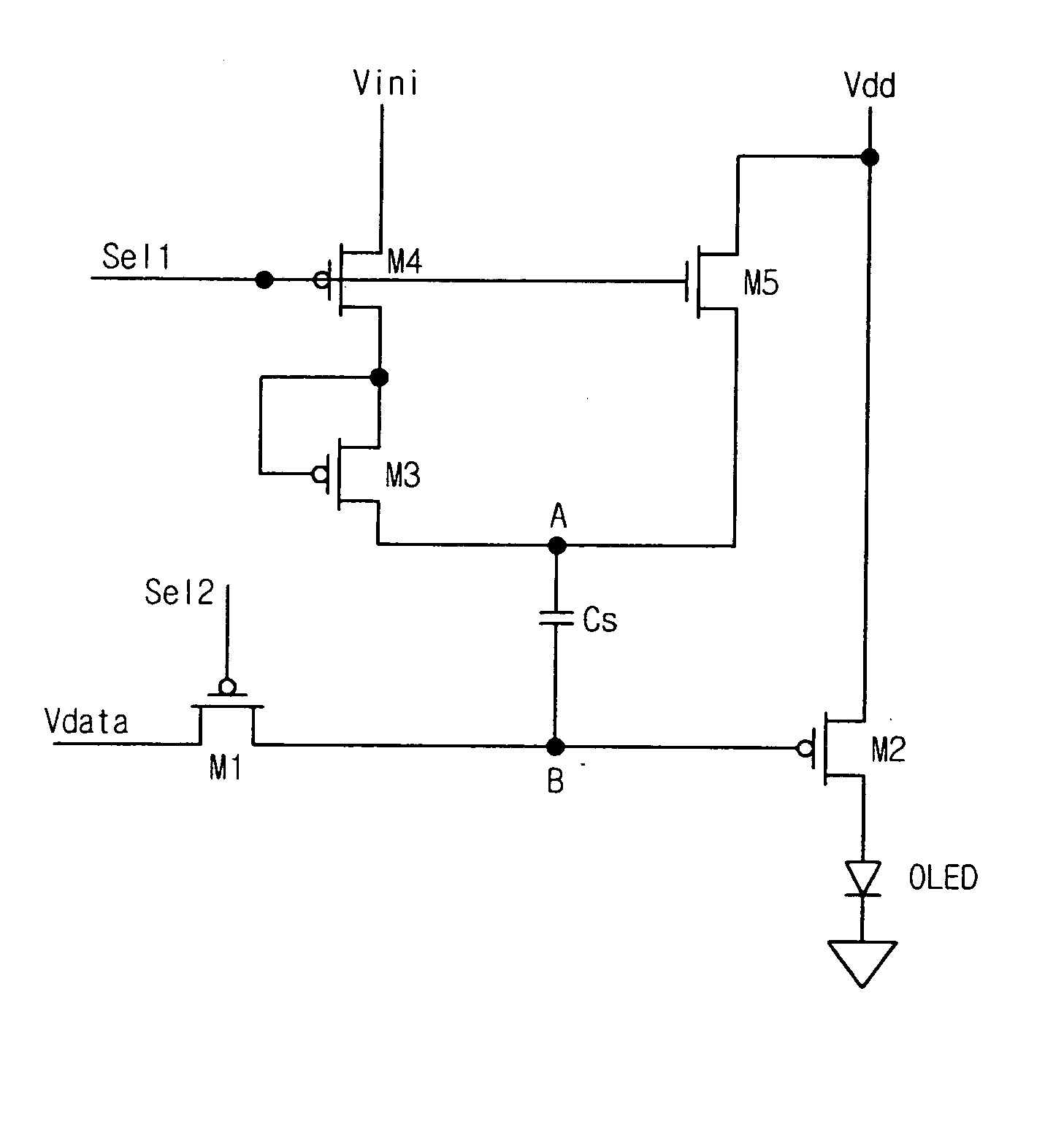
[0049]FIG. 4 illustrates a pixel of an organic light-emitting device according to the invention, which typically illustrates one of the N×M pixels.

[0050] Referring to FIG. 4, the inventive organic light-emitting device complementarily supplies a first selection signal (Sel1) to each of gate electrodes of fourth and fifth transistors M4 and M5. At this time, an initiation voltage (Vini) is supplied to a source electrode of the fourth transistor M4. A source electrode of a third transistor M3 connects to a drain electrode of the fourth transistor M4, and a first node (node A) connects to a drain electrode of the third transistor M3. Here, the fourth and fifth transistors M4 and M5 may have opposite polarities. Accordingly, if the first selection signal (Sel1) turns-on the fourth transistor M4, the fifth transistor M5 then turns-off. In contrast, if the fourth transistor M4 is turned-off, then the fifth transistor M5 is turned-on. That is, the signal to M4 is inverted in M5.

[0051] Whe...

second embodiment

[0078]FIG. 7 illustrates a pixel of an organic light-emitting device according to the invention, and typically illustrates one of N×M pixels.

[0079] The organic light-emitting device of the second embodiment of the invention shown in FIG. 7 has similarities with the organic light-emitting device according to the first embodiment of the invention shown in FIG. 4. However, the organic light-emitting device according to the first embodiment of the invention uses a CMOS transistor having opposite polarities as fourth and fifth transistors M4 and M5 to concurrently apply a first selection signal (Sel1) to the fourth and fifth transistors M4 and M5. That is, the fourth transistor M4 is composed of a PMOS transistor, and the fifth transistor M5 is composed of an NMOS transistor. Therefore, if the fourth transistor M4 is turned-on by the first selection signal (Sel1), then the fifth transistor M5 is turned-off.

[0080] In comparison, the organic light-emitting device according to the second e...

third embodiment

[0084]FIG. 8 shows a view illustrating a pixel of an organic light-emitting device according to the invention, and typically illustrates one of a display having N×M pixels.

[0085] The organic light-emitting device according to the second embodiment of the invention shown in FIG. 7 allows an organic light-emitting diode (OLED) to pass a high current during a first period (that is, reset period) for which a low reset voltage is applied by the second selection signal (Sel2). Accordingly, the organic light-emitting device has difficulty expressing a dark grayscale, and the device also has a reduced contrast ratio.

[0086] In the organic light-emitting device according to the third embodiment of the invention shown in FIG. 8, a sixth transistor M6 is connected between a second transistor M2 and the organic light-emitting diode (OLED), and the sixth transistor M6 is controlled by a separate fourth selection signal (Sel4). That is, a data voltage having a low reset voltage level is applied t...


PUM


Abstract

An organic light-emitting device includes a first transistor for applying a data voltage; a second transistor for applying a driving current depending on the data voltage and an initiation voltage to an organic light-emitting diode; a third transistor for generating a threshold voltage; a fourth transistor for applying an initiation voltage, the fourth transistor being connected to the third transistor; a fifth transistor for applying a power voltage; and a condenser provided between a first node connected to the third and fifth transistors and a second node connected to the first and second transistors, for maintaining the power voltage and the threshold voltage for compensation.

Description

BACKGROUND OF THE INVENTION [0001] 1. Field of the Invention [0002] The invention pertains to an organic light-emitting device, and more particularly, to an organic light-emitting device that prevents a stripe pattern caused by device irregularities and a power voltage drop, and improves the aperture ratio. [0003] 2. Description of the Related Art [0004] Generally, an organic light-emitting device is a self-emissive display device that emits light by electrically exciting a luminous organic compound. The organic light-emitting device can drive an NXM number of organic light-emitting diodes (OLEDs) to display an image. [0005] Driving the organic light-emitting device occurs in a passive matrix manner or in an active matrix manner using a transistor. The organic light-emitting device using the passive matrix manner is driven with an anode vertical to a cathode and a selection line. In comparison to the passive matrix driving, the organic light-emitting device using the active matrix i...

Claims


Application Information

Patent Timeline
IPC IPC(8): G09F9/30G09G3/30G09G3/32
CPCG09G3/3233G09G2300/0417G09G2300/0465G09G2300/0809G09G2320/043G09G2300/0842G09G2300/0861G09G2300/0876G09G2320/0233G09G2300/0819G01M99/004G01P15/097G01M7/06
Inventor KIM, BYEONG KOOKIM, O. HYUNPARK, YOUNG JU
Owner LG DISPLAY CO LTD
Why Eureka
Try Eureka