Electro-luminescence display device and method of driving the same

a technology of e-luminescence display and display device, applied in the field of e-luminescence display device, can solve the problems of large power consumption and complicated pixel structure, and achieve the effect of reducing power consumption

Active Publication Date: 2005-11-03
LG DISPLAY CO LTD
View PDF3 Cites 45 Cited by
  • Summary
  • Abstract
  • Description
  • Claims
  • Application Information

AI Technical Summary

Benefits of technology

[0013] An advantage of the present invention is to provide an electro-luminescence display device and a method of driving the same wherein a brightness of full white is controlled depending upon a brightness of an external environment, thereby controlling a brightness mode.
[0014] Another advantage of the present invention is to provide an electro-luminescence display device capable of reducing power consumption.

Problems solved by technology

However, such a surface-area divisional driving method has a problem in that the pixel structure becomes complicated.
Therefore, the related art EL display device driven by the time divisional driving method has a problem of large power consumption.

Method used


Image

  • Electro-luminescence display device and method of driving the same
  • Electro-luminescence display device and method of driving the same
  • Electro-luminescence display device and method of driving the same

Examples


first embodiment

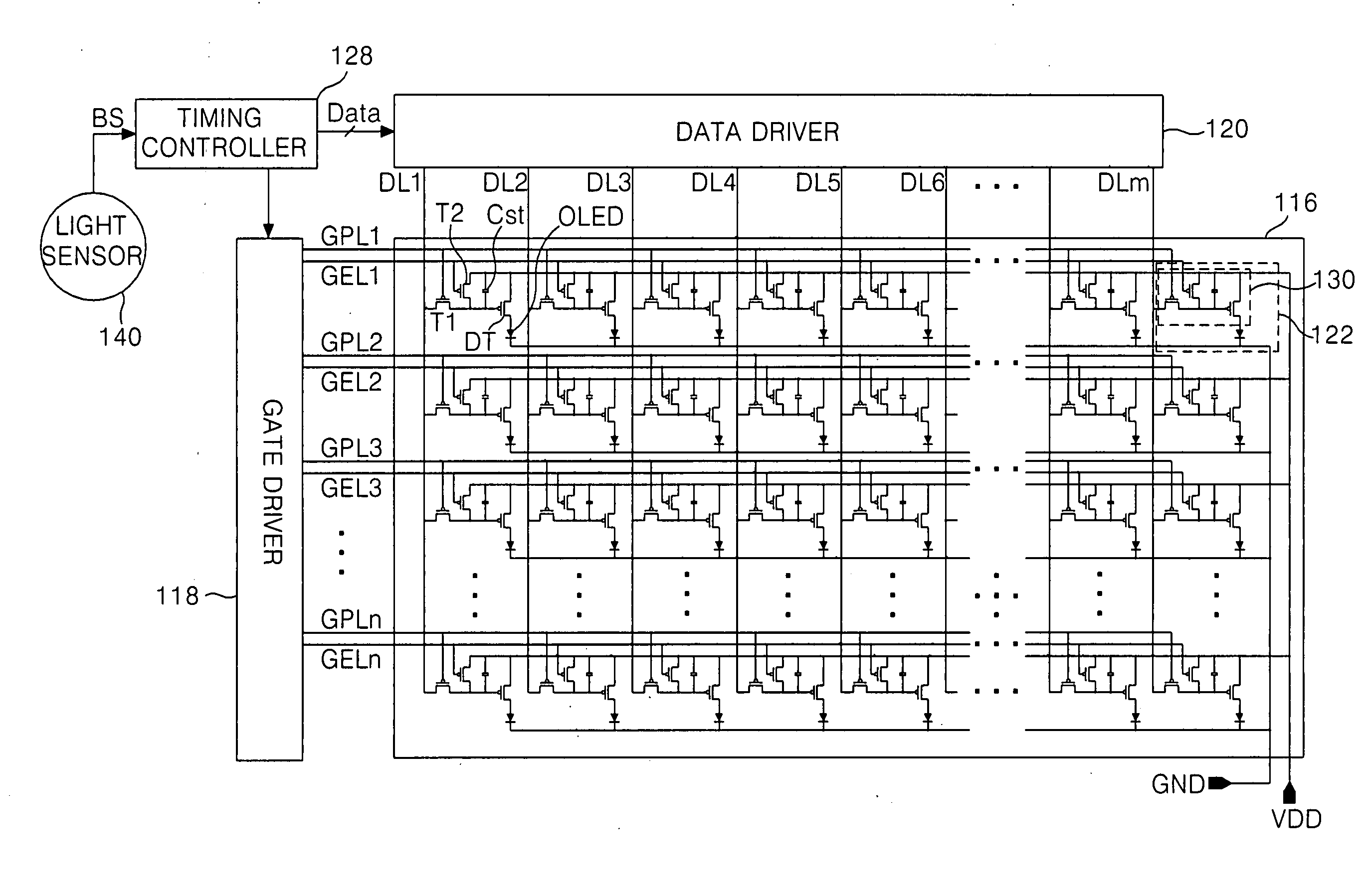
[0059] Referring to FIG. 3, an electro-luminescence (EL) display device according to the present invention includes an EL panel 116 having pixels 122 arranged at intersections among display gate lines GPL1 to GPLn and non-display gate lines GEL1 to GELn and data lines DL1 to DLm, a gate driver 118 for driving the display gate lines GPL1 to GPLn and the non-display gate lines GEL1 to GELn, a data driver 120 for driving the data lines DL1 to DLm, a photo sensor 140 for detecting a brightness of the external environment of the EL display panel 116, and a timing controller 128 for controlling a driving timing of the data driver 120 and the gate driver 118 and for applying a digital data Data to the data driver 120 in response to a brightness signal from the photo sensor 140.

[0060] Referring to FIG. 4, each pixel 122 includes a supply voltage source VDD, a ground voltage source GND, a light-emitting cell OELD connected between the supply voltage source VDD and the ground voltage source G...

second embodiment

[0080] For example, the look-up table (LUT) 254 converts the 6-bit digital data Data supplied from the exterior thereof into a 12-bit digital data MData having a 256 gray level information, and applies the converted digital data to the data driver 120, as indicated by the above-mentioned table 1. Herein, the 12 bits in the look-up table (LUT) 254 have a non-binary code or a weighting value of a binary code. the present invention will be described with an example of the binary code. For instance, a weighting value corresponding to each bit of the 12 bits has a ratio of 1:2:4:6:10:14:19:26:33:40:47:53. Accordingly, the 12-bit digital data MData converted by the look-up table (LUT) 254 and applied to the data driver 120 can express 256 gray levels, and a full white brightness corresponds to 255 digital data MData.

[0081] The gate control signal generator 260 generates the gate control signal GCS for generating a gate pulse GP for sequentially driving the display gate lines GPL1 to GPLn ...


PUM

PropertyMeasurementUnit
voltageaaaaaaaaaa
timeaaaaaaaaaa
brightnessaaaaaaaaaa

Abstract

An electro-luminescence display device and a method of driving the same for controlling a full white brightness depending upon a brightness of the external environment and thus controlling a brightness mode is disclosed. An electro-luminescence display device according to the present invention comprising: a display panel having pixels light-emitted by a supplied current; a data driver for applying a data voltage corresponding to said current to the pixels; and a timing controller for dividing one frame into a plurality of sub-frames and applying said data voltage corresponding to each of the plurality of sub-frames to the data driver and for controlling an emission time of each frame.

Description

[0001] This application claims the benefit of Korean Patent Application No. P2004-29867 filed in Korea on Apr. 29, 2004, which is hereby incorporated by reference for all purposes as if fully set forth herein. BACKGROUND OF THE INVENTION [0002] 1. Field of the Invention [0003] This invention relates to an electro-luminescence display, and more particularly to an electro-luminescence display device and a method of driving the same wherein a brightness of full white is controlled depending upon a brightness of external environment, thereby controlling a brightness mode. [0004] 2. Discussion of the Related Art [0005] An electro-luminescence (EL) display is a self-luminous device in which a phosphorous material emits light by recombination of electrons and holes. The EL display is largely classified into an inorganic EL display device and an organic EL display device, depending upon its material and structure. The EL display has the same advantage as cathode ray tubes (CRT) in that it h...

Claims


Application Information

Patent Timeline
Patent Type & Authority Applications(United States)
IPC IPC(8): C10B31/00G09G3/20G09G3/30H01L51/50H05B33/14
CPCG09G3/2022G09G3/2029G09G3/3258G09G3/3291G09G2300/0842G09G2360/144G09G2310/0262G09G2320/0276G09G2320/0626G09G2340/0428G09G2310/0251A44C5/0069A44C5/04A44C9/00A44C11/00A44C15/005A44C23/00A44C27/00B21L11/005
Inventor CHUNG, HOON JUJEON, CHANG HOON
Owner LG DISPLAY CO LTD
Why Eureka
Try Eureka